boss_notes/T-16_Power_Flow.md
8.4 KB · commit d2f3b6e
← T-15c: Torque-Speed Curves | 🏠 Index | T-17a: No-Load Test →
T-16: Power Flow & Rotor Power Division
Section: B | Priority: 🟡 MEDIUM | Exam Frequency: 2/7 years Sources: Theraja Ch-34 (Art. 34.33-34.38), VK Mehta Ch-8, Slides L-06
Why This Topic Matters
The power flow proof (Pg:PCu,r:Pm=1:s:(1−s)) appeared in 3 out of 7 papers (2018, 2023, 2024). The rotor efficiency proof (ηr=1−s) appeared in 2021 and 2023. The synchronous watt definition appeared in 2021. These are short, high-scoring proofs (3-4 marks each). The power flow numerical appeared in 2020.
📝 Key Definitions
Air-Gap Power (Pg): "The power transferred from the stator to the rotor across the air gap is called the air-gap power. It is given by Pg=3I22R2/s." — Theraja, Art. 34.34
Synchronous Watt: "A synchronous watt is the torque which, at the synchronous speed of the machine under consideration, would give a power dissipation of 1 watt. Torque in synchronous watts equals the air-gap power in watts." — Theraja, Art. 34.35
Rotor Efficiency: "The rotor efficiency is the ratio of the mechanical power developed to the air-gap power: ηrotor=(1−s)." — VK Mehta, Ch-8
Power Flow Diagram
Stator Input P1−Ps,Cu−PFeAir-gap Pg−Pr,CuMech Power Pm−Pf&wOutput Pout
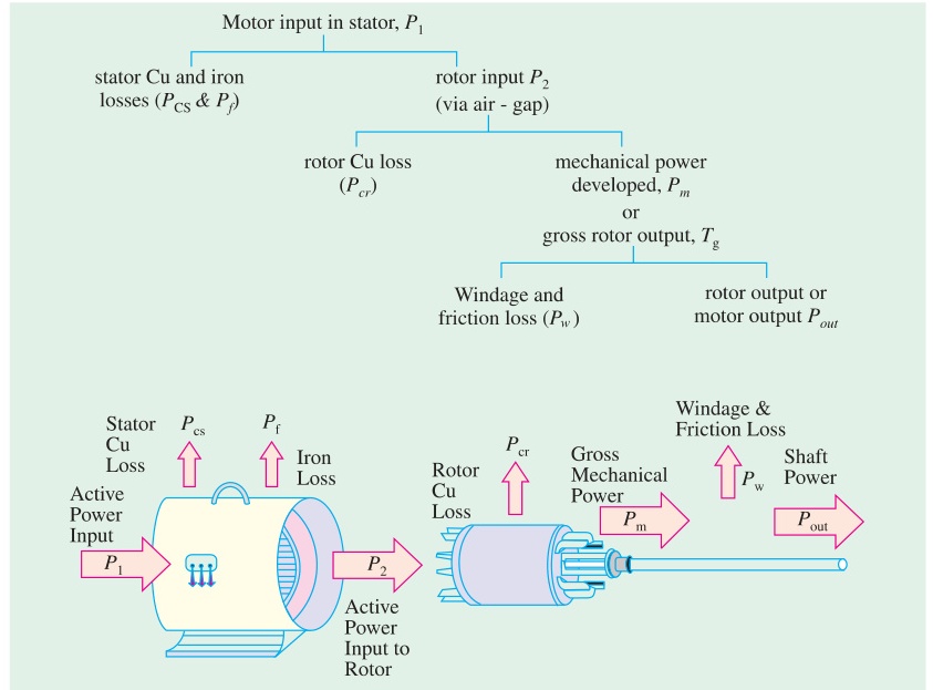
From the equivalent circuit:
- Stator input: P1=3V1I1cosϕ1
- Stator copper loss: Ps,Cu=3I12R1
- Stator iron loss: PFe≈3E12/Rc
- Air-gap power: Pg=P1−Ps,Cu−PFe=3I22⋅R2/s
- Rotor copper loss: Pr,Cu=3I22R2
- Mechanical power: Pm=Pg−Pr,Cu=3I22R2(1−s)/s
- Output: Pout=Pm−Pf&w−Pstray
The Golden Power Ratio
This is the most important relationship in IM power analysis.
Proof: PCu,r=sPg
From the equivalent circuit:
Pg=3I22⋅sR2
PCu,r=3I22R2=s⋅3I22⋅sR2=s⋅Pg
PCu,r=sPg
Mechanical power:
Pm=Pg−PCu,r=Pg−sPg=(1−s)Pg
The ratio:
Pg:PCu,r:Pm=1:s:(1−s)
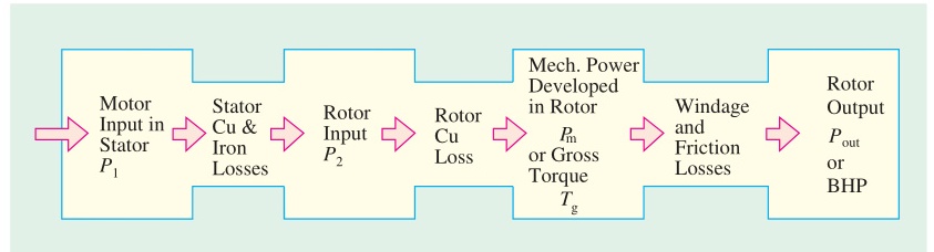
Physical meaning: For every 1 watt crossing the air gap, s watts become rotor heat and (1−s) watts become mechanical power. At s=0.04 (typical full load), 96% of air-gap power becomes mechanical, 4% becomes heat.
Rotor Efficiency
ηrotor=PgPm=Pg(1−s)Pg=(1−s)
At s=0.04: ηrotor=96%. This is why induction motors run at low slip.
Synchronous Watt
One synchronous watt is the torque that develops one watt of power at synchronous speed.
T (synchronous watts)=Pg (watts)
To convert to N-m:
T=ωsPg=2πNs/60Pg N-m
Example: Pg=5000 W, Ns=1000 rpm:
T=2π×1000/605000=104.75000=47.75 N-m
Worked Example (PYQ 2020)
2020 Q6(d): 400V, 50 Hz, 6-pole IM. Pg=75 kW. Rotor EMF makes 100 alternations per minute. Find slip, rotor speed, Cu losses per phase, mechanical power.
Rotor frequency: fr=100/60=5/3 Hz
(i) Slip: s=fr/f=(5/3)/50=1/30=0.0333=3.33%
(ii) Rotor speed: Ns=120×50/6=1000 rpm
N=Ns(1−s)=1000(1−0.0333)=966.7 rpm
(iii) Rotor Cu losses (total): PCu,r=sPg=0.0333×75000=2500 W
Per phase: PCu,r/3=833.3 W
(iv) Mechanical power: Pm=(1−s)Pg=0.9667×75000=72500 W=72.5 kW
🏆 Golden Questions (Past Exam Archive)
🎯 Q1: Show that rotor copper loss = s× air-gap power. Also show Pm:PCu,r:Pg=(1−s):s:1.
Appeared: 2018 Q5(b), 2023 Q6(a), 2024 Q5(b) — (4 marks)
Full Answer:
From the equivalent circuit, air-gap power: Pg=3I22⋅R2/s
Rotor copper loss: PCu,r=3I22R2=s⋅3I22⋅R2/s=sPg
PCu,r=sPg
Mechanical power: Pm=Pg−PCu,r=Pg−sPg=(1−s)Pg
Pm:PCu,r:Pg=(1−s)Pg:sPg:Pg=(1−s):s:1
🎯 Q2: What is rotor efficiency? Show that ηrotor=(1−s).
Appeared: 2021 Q6(c), 2023 Q6(c) — (3-4 marks)
Full Answer:
Rotor efficiency is the ratio of mechanical power developed to electrical power input to the rotor (air-gap power).
ηrotor=PgPm=Pg(1−s)Pg=(1−s)
At s=0.04 (typical full load): ηrotor=96%.
For every unit of power crossing the air gap, fraction s is wasted as rotor copper heat and fraction (1−s) becomes mechanical work. Low slip means high rotor efficiency. This is why induction motors are designed to operate at small slip.
🎯 Q3: Define synchronous watt with an example.
Appeared: 2021 Q8(a) — (3 marks)
Full Answer:
Synchronous watt: A unit of torque used in induction motor analysis. One synchronous watt is the torque that develops one watt of power at synchronous speed.
T (synchronous watts)=Pg (watts)
Conversion: T(N-m)=Pg/ωs=Pg/(2πNs/60)
Example: Motor has Pg=5000 W, Ns=1000 rpm (ωs=104.7 rad/s):
T=5000/104.7=47.75 N-m
The torque is 5000 synchronous watts, which equals 47.75 N-m at this synchronous speed.
🎯 Q4: Derive power equations of an induction motor from equivalent circuit.
Appeared: 2020 Q6(b) — (4 marks)
Full Answer:
From the per-phase equivalent circuit:
Stator input: P1=3V1I1cosϕ1
Stator copper loss: Ps,Cu=3I12R1
Stator iron loss: PFe≈3V12/Rc
Air-gap power: Pg=P1−Ps,Cu−PFe=3I22⋅R2/s
Rotor copper loss: PCu,r=3I22R2=sPg
Mechanical power: Pm=Pg−PCu,r=(1−s)Pg=3I22R2(1−s)/s
Output: Pout=Pm−Pf&w
Summary: Pg:PCu,r:Pm=1:s:(1−s)
🎯 Q5: Motor driving constant-torque load. Voltage drops to 90%. Find increase in Cu losses.
Appeared: 2021 Q6(b) — (4 marks)
Full Answer:
For small slip (low-slip approximation): T≈kE22s/R2∝sV2/R2
At constant torque: s1V12=s2V22
s2=s1(V1/V2)2=s1×(1/0.9)2=s1×1.2346
Rotor Cu loss: PCu=sPg, and Pg=Tωs (constant).
PCu,new/PCu,old=s2/s1=1.2346
Increase: (1.2346−1)×100%=23.46%
Cu losses increase by about 23.5% when voltage drops to 90%.
Exam Variants
| Year | Question | Key Result |
|---|---|---|
| 2018 Q5(b) | Show PCu,r=sPg | Proof |
| 2020 Q6(b) | Derive power equations | Full chain |
| 2020 Q6(d) | Power flow numerical | s=3.33%, Pm=72.5 kW |
| 2021 Q6(b) | 90% voltage, Cu loss increase | 23.46% increase |
| 2021 Q6(c) | Rotor efficiency | ηr=1−s |
| 2021 Q8(a) | Synchronous watt | Definition + example |
| 2023 Q6(a) | Show power ratio | 1:s:(1−s) |
| 2023 Q6(c) | Rotor efficiency proof | ηr=1−s |
| 2024 Q5(b) | Show PCu,r=sPg + ratio | Same proof |
⚡ Exam Tips & Common Mistakes
- The ratio is 1:s:(1−s), not 1:(1−s):s. Air gap : Cu loss : Mechanical. Don't swap the last two.
- Rotor efficiency is (1−s), not (1−s)%. Express as per-unit or convert explicitly.
- Synchronous watt is numerically equal to Pg in watts. The conversion to N-m requires dividing by ωs.
- For power flow numericals: Always start by finding slip from rotor frequency (s=fr/f).
🔗 Related Topics
- T-14: IM Equivalent Circuit — Source of power equations
- T-15b: Running & Max Torque — Torque from air-gap power
- T-17a: No-Load Test — Measures fixed losses
← T-15c: Torque-Speed Curves | 🏠 Index | T-17a: No-Load Test →