boss_notes/T-17a_No_Load_Test.md
5.5 KB · commit d2f3b6e
← T-16: Power Flow | 🏠 Index | T-17b: Blocked Rotor Test →
T-17a: No-Load Test (IM)
Section: B | Priority: 🟠 HIGH | Exam Frequency: 4/7 years Sources: Theraja Ch-35 (Art. 35.3-35.5), VK Mehta Ch-8, Slides L-05
Why This Topic Matters
The no-load test explanation appeared in 4 out of 7 papers (2019, 2021, 2023, 2024). It is always paired with the blocked rotor test. Together they are worth 4-9 marks. The no-load test provides the shunt branch parameters (Rc, Xm) and the no-load losses. This test is also an input to the circle diagram.
📝 Key Definitions
No-Load Test: "The motor is run at no-load (no mechanical load on shaft) at rated voltage and frequency. Since the slip is very nearly zero, the rotor branch in the equivalent circuit is effectively an open circuit. The motor draws only a small no-load current to supply core loss and friction/windage losses." — Theraja, Art. 35.3
Test Setup and Procedure
- Connect the motor to rated 3-phase supply at rated voltage V0 and rated frequency f.
- Run the motor with no mechanical load on the shaft.
- Measure: line voltage V0, line current I0, total 3-phase input power P0.
What happens at no-load:
- Slip s≈0 (typically 0.001 to 0.005)
- Since s≈0: R2/s→∞. The rotor branch is effectively open-circuited.
- The motor draws only no-load current I0 (5-10% of rated current).
- Input power P0 covers: stator core loss + friction and windage + small stator I2R loss.
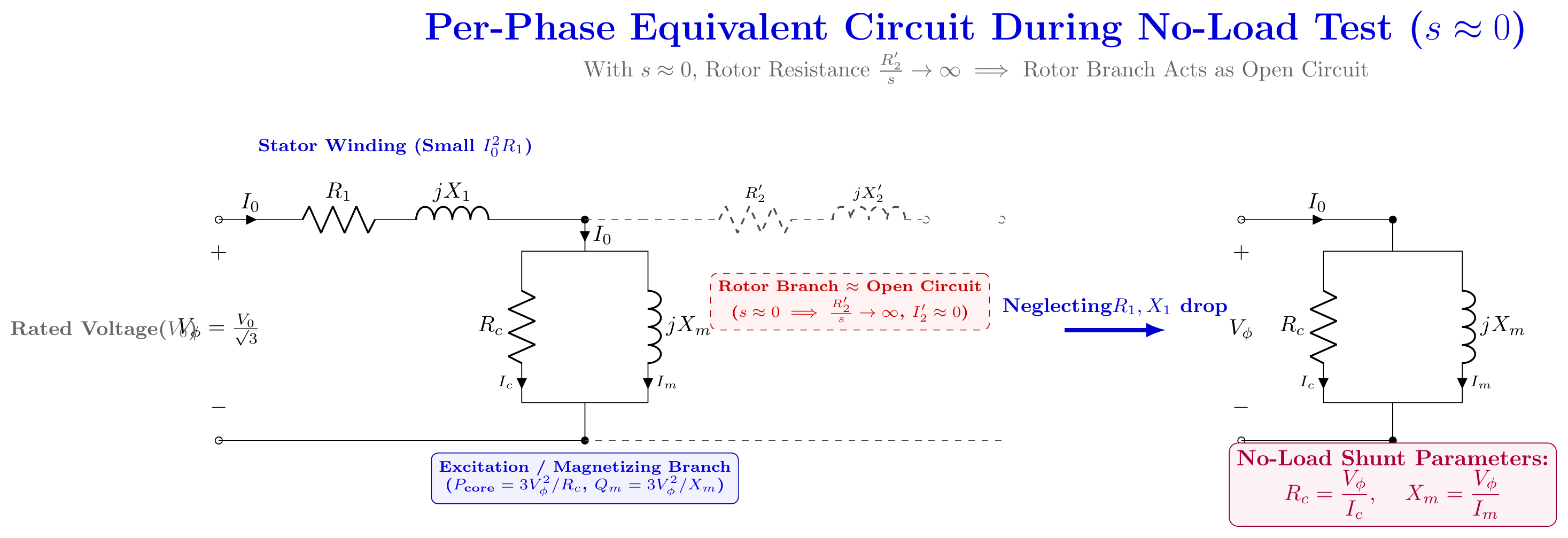
Parameters from No-Load Test
No-load power factor:
cosϕ0=3V0I0P0
No-load current components:
Ic=I0cosϕ0(core-loss component)
Im=I0sinϕ0(magnetizing component)
Shunt branch parameters (per phase):
Rc=IcVϕ,Xm=ImVϕ
where Vϕ=V0/3 for star connection and Vϕ=V0 for delta.
Rotational losses:
Prot=P0−3I02R1
where R1 is the stator resistance per phase (from DC test). The term 3I02R1 is the small stator copper loss at no-load.
🏆 Golden Questions (Past Exam Archive)
🎯 Q1: Explain the no-load and blocked rotor tests for a 3-phase IM. Determine the equivalent circuit parameters.
Appeared: 2023 Q7(a), 2024 Q7(a) — (9 marks)
Full Answer:
No-Load Test:
Motor runs uncoupled at rated voltage and frequency. Since s≈0, the rotor branch is effectively open. The motor draws a small no-load current I0.
Measurements: V0 (line voltage), I0 (line current), P0 (3-phase power).
Parameters found: Shunt branch (Rc, Xm).
cosϕ0=3V0I0P0
Ic=I0cosϕ0,Im=I0sinϕ0
Rc=Vϕ/Ic,Xm=Vϕ/Im
Rotational losses: Prot=P0−3I02R1
Blocked-Rotor Test: (See T-17b for full details)
Rotor locked (s=1). Reduced voltage applied until rated current flows. Measure Vsc, Isc, Psc.
Z01=IscVsc/3,R01=3Isc2Psc,X01=Z012−R012
R2′=R01−R1,X1=X2′=X01/2
DC Test (for R1): Apply DC between two stator terminals. For star: R1=RDC/2. For delta: R1=1.5RDC.
🎯 Q2: Describe the no-load test. What does plugging mean?
Appeared: 2019 Q7(a) — (4 marks)
Full Answer:
No-load test: Motor runs at no-load, rated voltage and frequency. Measure V0, I0, P0. Since s≈0, rotor branch is open. P0 gives core loss + friction/windage. The no-load power factor is very low (0.1-0.2) because the current is mostly magnetizing.
Parameters: Rc=Vϕ/Ic and Xm=Vϕ/Im.
Plugging: A braking method. The phase sequence of the stator supply is reversed while the motor is running. The stator field now rotates opposite to the rotor. A braking torque opposes motion. The motor decelerates rapidly. Supply must be cut before zero speed, or the motor reverses direction.
Exam Variants
| Year | Question | Marks | Paired With |
|---|---|---|---|
| 2019 Q7(a) | Describe NL test + define plugging | 4 | Plugging definition |
| 2023 Q7(a) | Explain NL + BR tests, find parameters | 9 | Blocked rotor test |
| 2024 Q7(a) | Explain NL + BR tests, find parameters | 9 | Blocked rotor test |
⚡ Exam Tips & Common Mistakes
- No-load test gives the SHUNT branch (Rc, Xm). Blocked rotor test gives the SERIES branch (R01, X01).
- Don't forget the stator I2R correction. Prot=P0−3I02R1, not just P0.
- No-load power factor is very low (0.08-0.2). The current is mostly magnetizing.
- For delta connection: Vϕ=V0 (line voltage = phase voltage). For star: Vϕ=V0/3.
🔗 Related Topics
- T-17b: Blocked Rotor Test — Always paired with NL test
- T-14: IM Equivalent Circuit — Circuit that these tests determine
- T-18: Circle Diagram — Uses NL + BR test data