boss_notes/T-14_IM_Equivalent_Circuit.md
7.1 KB · commit d2f3b6e
← T-13: Slip & Basics | 🏠 Index | T-15a: Starting Torque →
T-14: IM Equivalent Circuit
Section: B | Priority: 🟠 HIGH | Exam Frequency: 3/7 years Sources: Theraja Ch-34 (Art. 34.47), VK Mehta Ch-8 (Art. 8.8-8.9), Chapman Ch-7, Slides L-03
Why This Topic Matters
The equivalent circuit question appeared in 3 out of 7 papers (2017, 2020, 2023). It is worth 3-6 marks per appearance. More importantly, every torque and power calculation in Section B relies on this circuit. If you can draw the 6-step equivalent circuit development, you can answer any IM analysis question.
📝 Key Definitions
Equivalent Circuit of IM: "An induction motor can be treated as a rotating transformer i.e. one in which primary winding is stationary but the secondary is free to rotate." — Theraja, Art. 34.2. The equivalent circuit represents the per-phase electrical model of this rotating transformer.
Load Resistance RL: "The resistance R2(1−s)/s represents the electrical equivalent of the gross mechanical power developed by the motor." — VK Mehta, Art. 8.9
Step-by-Step Equivalent Circuit Development
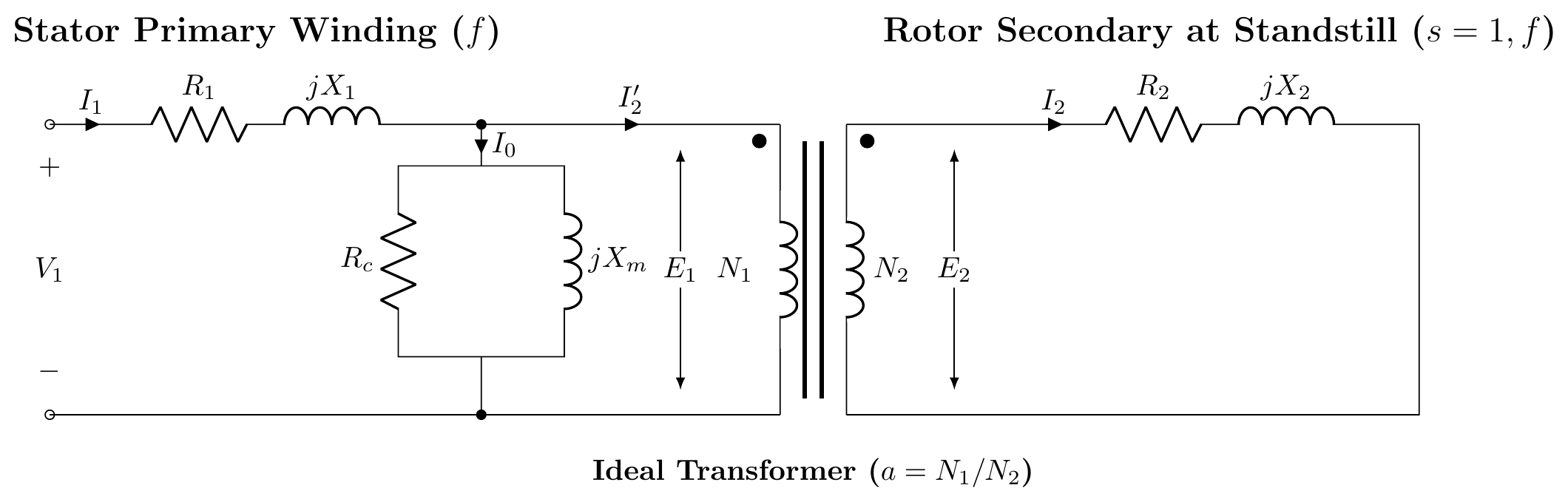
Step 1: Transformer Model at Standstill (s=1)
At standstill, the IM acts exactly like a transformer. The stator is the primary. The rotor is the short-circuited secondary.
- Stator: resistance R1, leakage reactance X1
- Shunt branch: core loss resistance Rc, magnetizing reactance Xm
- Rotor: resistance R2, standstill reactance X2
Step 2: Rotor at Running Slip s
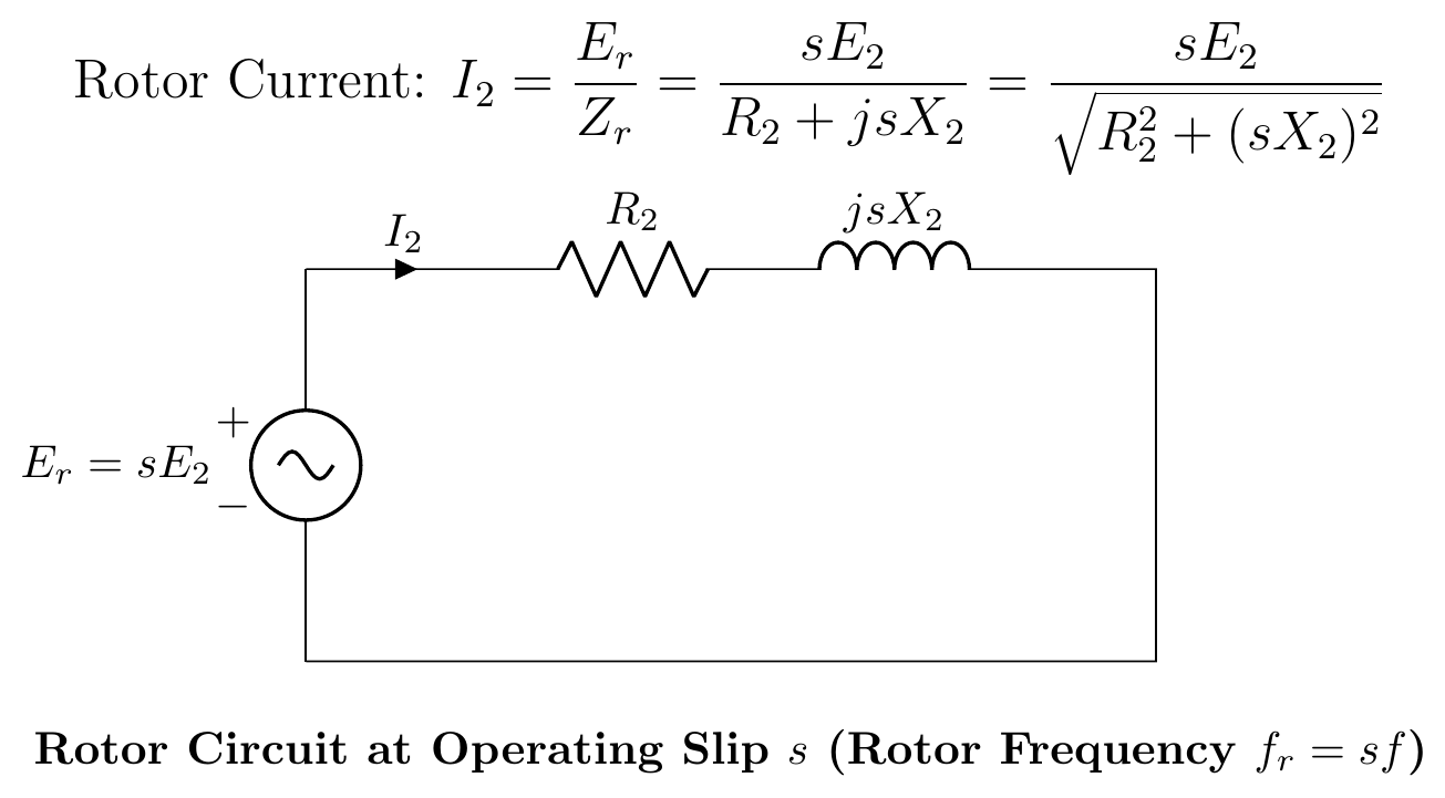
When running at slip s, the rotor frequency changes to sf. The rotor EMF and reactance scale with slip:
E2s=sE2,X2s=sX2
Rotor current:
I2=R2+jsX2sE2=R22+(sX2)2sE2
Step 3: Frequency Transformation
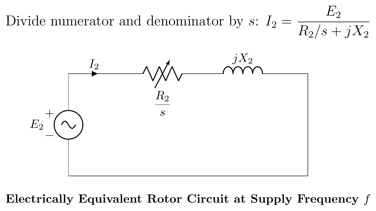
Divide numerator and denominator of the rotor current equation by s:
I2=R2/s+jX2E2
This transforms the rotor to the stator frequency f. The rotor resistance appears as a variable resistance R2/s at the stator frequency.
Step 4: Power Separation
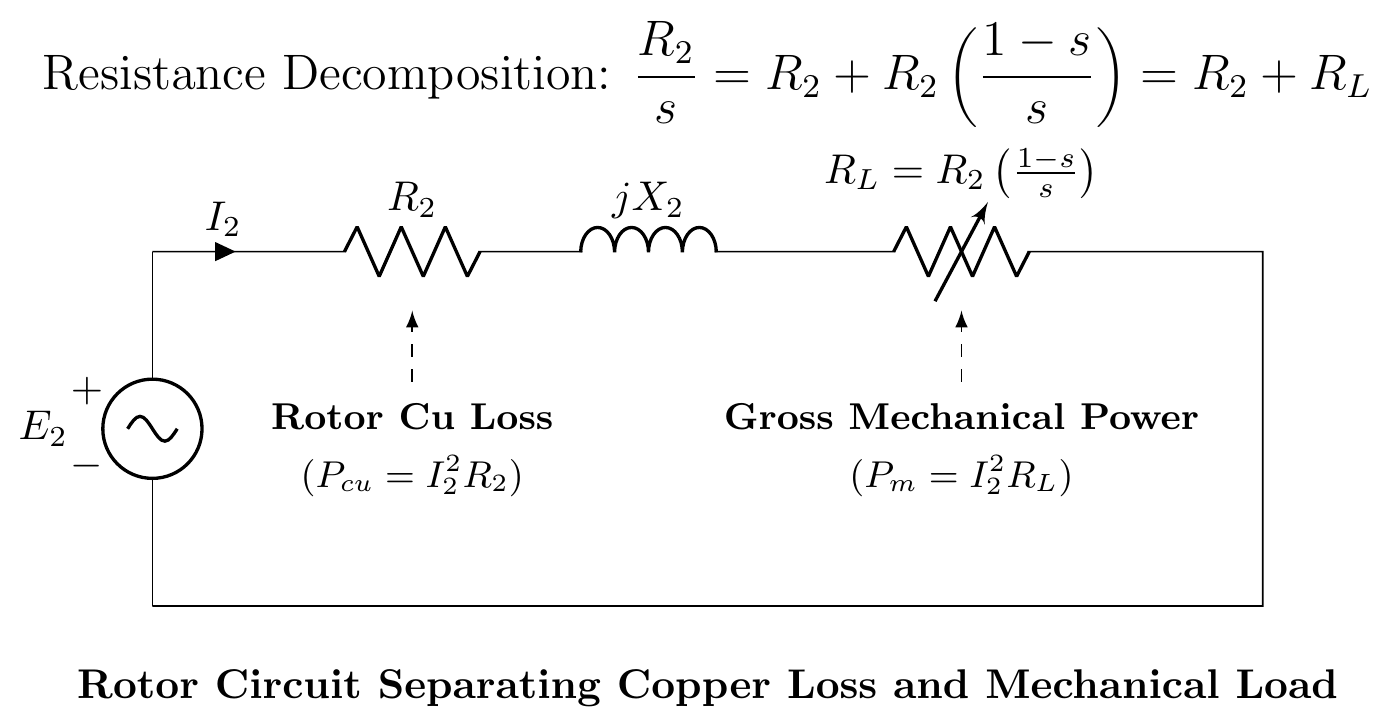
Split R2/s into two parts:
sR2=R2+R2(s1−s)
- R2 represents actual rotor copper loss (heat)
- RL=R2(1−s)/s represents the mechanical load (gross mechanical power)
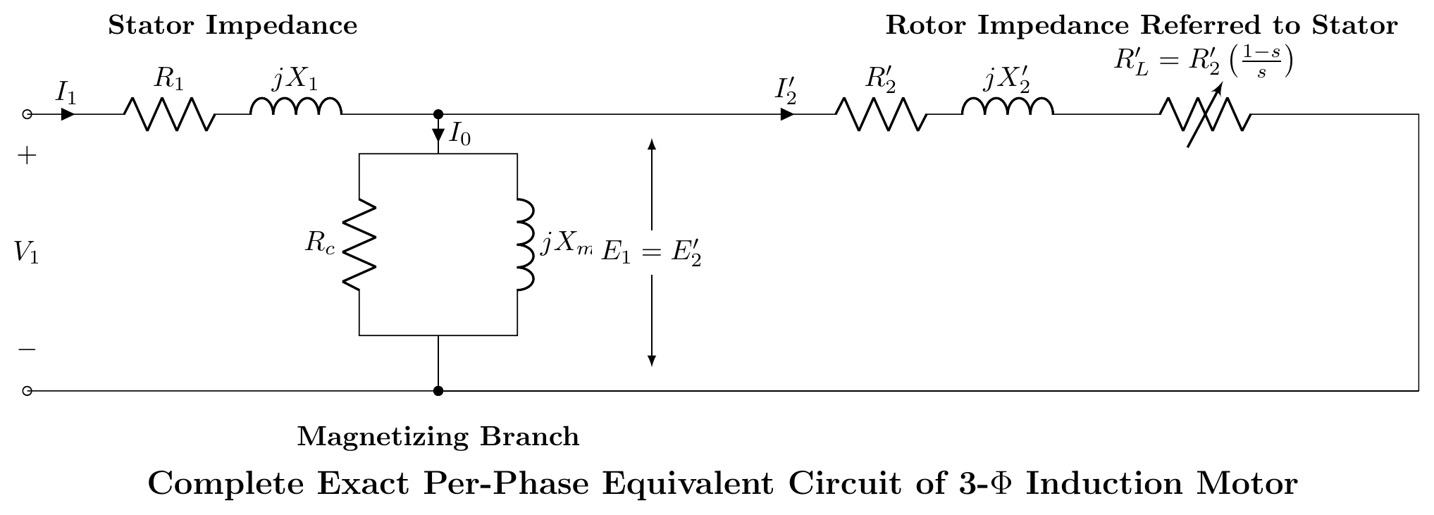
Step 5: Exact Equivalent Circuit (Referred to Stator)
Refer all rotor quantities to the stator using the effective turns ratio a=N1/N2:
R2′=a2R2,X2′=a2X2,RL′=R2′(s1−s)
Step 6: Approximate Equivalent Circuit
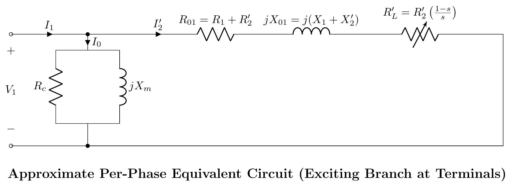
Since the stator voltage drop is small (typically < 5%), the shunt branch (Rc, Xm) can be moved to the input terminals. This simplifies calculations without much loss of accuracy.
Key Equations from the Equivalent Circuit
Air-gap power (per phase):
Pg=I22⋅sR2
Total air-gap power (3-phase):
Pg=3I22⋅sR2
Rotor copper loss:
PCu,r=3I22R2=sPg
Mechanical power:
Pm=Pg−PCu,r=(1−s)Pg=3I22R2s(1−s)
🏆 Golden Questions (Past Exam Archive)
🎯 Q1: Draw the step-by-step equivalent circuit of a 3-phase induction motor.
Appeared: 2017 Q3(a), 2020 Q5(c) — (3-6 marks)
Full Answer:
See Step-by-Step Equivalent Circuit Development above for the complete 6-step development:
- Standstill transformer model: Stator (R1,X1) + shunt (Rc,Xm) + rotor (R2,X2)
- Running rotor: EMF becomes sE2, reactance becomes sX2
- Frequency transformation: Divide by s to get R2/s at stator frequency
- Power separation: R2/s=R2+R2(1−s)/s, where R2(1−s)/s is mechanical load
- Refer to stator: R2′=a2R2, X2′=a2X2
- Approximate circuit: Move shunt branch to input terminals
🎯 Q2: How can the equivalent circuit model of an induction motor be obtained?
Appeared: 2020 Q5(c) — (6 marks)
Full Answer:
The equivalent circuit of an IM is obtained by treating it as a rotating transformer.
Starting point: At standstill (s=1), the IM is identical to a transformer. The stator is the primary with impedance Z1=R1+jX1. The shunt branch models core losses (Rc) and magnetizing current (Xm). The rotor is the short-circuited secondary with impedance Z2=R2+jX2.
Running modification: When the rotor spins at slip s, two things change: (a) rotor EMF reduces to sE2, (b) rotor reactance reduces to sX2.
Key trick: The rotor current equation I2=sE2/R22+(sX2)2 can be rewritten as I2=E2/(R2/s)2+X22 by dividing top and bottom by s. This transforms the rotor circuit to stator frequency. The resistance R2/s splits as R2+R2(1−s)/s, where R2 accounts for copper loss and R2(1−s)/s represents mechanical power.
Final step: Refer all rotor quantities to the stator using a2 scaling. Move shunt branch to input for the approximate circuit.
Exam Variants
| Year | Question | Marks | Focus |
|---|---|---|---|
| 2017 Q3(a) | Draw step-by-step equivalent circuit | 3 | All 6 steps |
| 2020 Q5(c) | How to obtain eq. circuit model? | 6 | Derivation + explanation |
| 2023 Q7(a) | Explain NL and BR tests, find parameters | 9 | Testing + circuit |
⚡ Exam Tips & Common Mistakes
- Draw ALL six steps. Don't jump to the final circuit. Each step carries marks.
- Label R2(1−s)/s clearly. This is the mechanical load, not just a resistor.
- R2/s is NOT the rotor resistance. It is the total impedance that accounts for both copper loss and mechanical power.
- The shunt branch is NOT negligible. In the exact circuit, it sits between Z1 and Z2′. Only move it for the approximate circuit.
- Know both exact and approximate circuits. Some questions ask specifically for one or the other.
🔗 Related Topics
- T-13: Slip & Basics — Slip determines all rotor quantities
- T-15a: Starting Torque — Torque from the equivalent circuit
- T-16: Power Flow — Power stages from the circuit
- T-17a: No-Load Test — Finding shunt branch parameters
- T-17b: Blocked Rotor Test — Finding series branch parameters