answers_explanation/2019_answer.md
26.0 KB · commit d2f3b6e
← 2018 Answer | 🏠 Index | 2020 Answer →
ECE 2207: 2019 Semester Final: Explanation Style Answers
RUET · ECE Dept · 2nd Year Odd Semester 2019
Deep tutorial-style explanations focusing on first-principles physics, "why over what", step-by-step logic, and practical engineering intuition. Core cross-cutting theory topics are detailed in 2018_2024_answer.md.
SECTION - A (Transformers: Q1 to Q4)
Question 1
Q1(a): Transformer Energy Transfer and Winding Classification
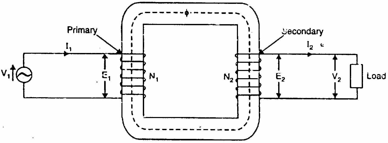
- Definition: A static electromagnetic device that transfers alternating electrical energy between two or more electrically isolated circuits through mutual magnetic flux linkage, at constant frequency.
- Energy Transfer Mechanism: When primary voltage v1(t) is applied, it drives an alternating primary current that establishes an oscillating magnetic flux in the laminated iron core. By Faraday's Law of Induction, this core flux cuts the secondary winding, inducing secondary EMF e2(t). When an external load is connected, secondary current flows, delivering electrical power to the load across the magnetic medium without any conductive contact.
- Distinction between Primary and Secondary:
- Primary Winding: The winding connected to the electrical source (input). It draws energy from the grid.
- Secondary Winding: The winding connected to the load (output). It delivers energy to the consumer. (Note: A winding is not intrinsically "primary" or "secondary" by construction—its role is defined entirely by whether it is connected to the source or load).
Q1(b): Induced EMF Derivation and EMF per Turn Equality
For complete mathematical derivation see T-01: EMF Equation: E=4.44fNΦm.
- Peak induced EMF: Em=ωNΦm=2πfNΦm.
- RMS induced EMF: E=2Em=2πfNΦm≈4.44fNΦm.
- Why EMF per turn is strictly equal: N1E1=4.44fΦm=N2E2 Because every individual turn of wire on both coils encircles the exact same shared magnetic core flux Φ(t), each turn experiences the identical instantaneous rate of change of flux (−dtdΦ). Hence, volts-per-turn is an invariant geometric and magnetic property of the core.
Q1(c): Why Does Primary Current Increase With Secondary Load?
The Fundamental Principle: MMF Balance and Flux Invariance
An AC transformer core maintains its mutual operating flux Φm essentially constant from no-load to full-load, governed by the applied supply voltage: Φm≈4.44fN1V1
- At No-Load (I2=0): The primary draws only the small no-load current I0 (2–5% of rated). The primary MMF (N1I0) provides the magnetic force needed to establish and maintain Φm in the core.
- When Secondary Load Current Flows (I2>0): The load current flowing through N2 turns creates a secondary MMF: F2=N2I2 By Lenz's Law, this secondary MMF directly opposes and demagnetizes the core flux Φm.
- Primary Self-Regulating Action: The moment Φm tends to drop, the primary counter-EMF E1=4.44fN1Φm decreases slightly. Because V1 is maintained constant by the grid, the net driving voltage (V1−E1) increases, immediately pulling an additional compensating current I2′ from the supply.
- Restoring MMF Equilibrium: The primary draws balancing current I2′ such that its MMF cancels the secondary demagnetizing MMF completely: N1I2′+N2I2=0⟹I2′=−N1N2I2 Total primary current is the phasor sum: I1=I0+I2′=I0+N1N2I2 As secondary load current I2 rises, the primary automatically draws a proportionally larger reflected current from the supply to maintain constant core flux and conserve energy.
Question 2
Q2(a): Open-Circuit and Short-Circuit Tests
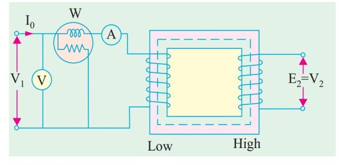
- Open-Circuit Test (Conducted on LV side, HV open): Rated voltage is applied to the LV winding. Because I2=0, primary draws only no-load current I0 (negligible copper loss). The wattmeter reading W0 measures purely core loss (PFe=Ph+Pe). Extracts shunt parameters: cosϕ0=V0I0W0,Rc=I0cosϕ0V0,Xm=I0sinϕ0V0
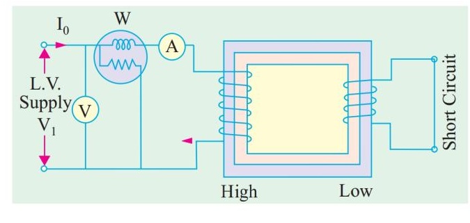
- Short-Circuit Test (Conducted on HV side, LV shorted): A tiny voltage (~5–10% rated) is applied to circulate rated current. Because voltage is low, core flux is negligible (Φ∝Vsc), making core loss practically zero. The wattmeter reading Wsc measures purely full-load copper loss (PCu,FL). Extracts series parameters: Z01=IscVsc,R01=Isc2Wsc,X01=Z012−R012
Q2(b): Voltage Regulation for Lagging, Unity, and Leading Loads
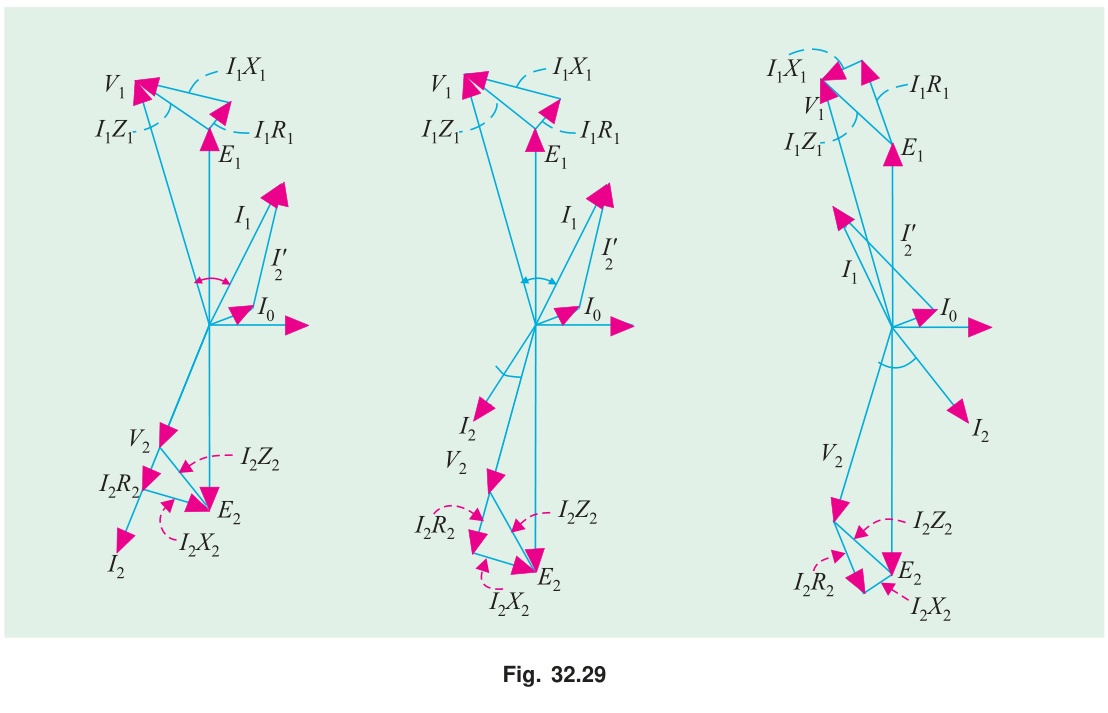
VR%≈V2,ratedI2(R02cosϕ2±X02sinϕ2)×100%
- Lagging PF Load (Inductive): Current lags voltage. The reactive drop jI2X02 points forward in phase with the resistive drop, subtracting from terminal voltage. ΔV is large and positive, causing substantial voltage drop (VR is positive and maximum).
- Unity PF Load (Pure Resistive): sinϕ2=0. The reactive drop is in quadrature with V2, causing primarily a small phase shift rather than a magnitude drop. ΔV≈I2R02 (VR is positive but small).
- Leading PF Load (Capacitive): Current leads voltage. The reactive drop jI2X02 rotates backward, opposing the resistive drop. If X02sinϕ2>R02cosϕ2, secondary terminal voltage rises above no-load EMF (V2>E2). ΔV is negative (negative VR / voltage rise).
Q2(c): Numerical Efficiency Calculation (10 kVA, 2200/220V)
Given Data:
- Rating S=10 kVA=10,000 VA
- OC Test: PFe=153 W (constant at all loads)
- SC Test: Full-load copper loss PCu,FL=224 W
1. Full-Load Efficiency (x=1.0):
- At Unity Power Factor (cosϕ=1.0): Pout=10,000×1.0=10,000 W Ploss=PFe+PCu,FL=153+224=377 W η=10,000+37710,000×100%=10,37710,000×100%=96.37%
- At 0.8 PF Lagging (cosϕ=0.8): Pout=10,000×0.8=8,000 W Ploss=377 W η=8,000+3778,000×100%=8,3778,000×100%=95.50%
2. Half-Load Efficiency (x=0.5):
- Copper loss at half-load: PCu=x2PCu,FL=(0.5)2×224=0.25×224=56 W.
- Total losses at half-load: Ploss=153+56=209 W.
- At Unity Power Factor (cosϕ=1.0): Pout=0.5×10,000×1.0=5,000 W η=5,000+2095,000×100%=5,2095,000×100%=95.99%
- At 0.8 PF Lagging (cosϕ=0.8): Pout=0.5×10,000×0.8=4,000 W η=4,000+2094,000×100%=4,2094,000×100%=95.03%
Question 3
Q3(a): Transformer Breathing and Maximum Efficiency Proof
Transformer Breathing:
As transformer electrical load fluctuates, winding and core losses heat up the insulating oil. The dielectric oil expands as its temperature rises and contracts as it cools. In conservator-tank transformers, this volume change forces air to be expelled into the atmosphere when hot and sucked into the conservator when cool. This cyclic inhalation and exhalation of air is called transformer breathing.
- To prevent humid atmospheric air from contaminating the oil, the air passes through a silica gel breather. Dehydrated silica gel crystals absorb atmospheric moisture (turning from deep blue to pale pink), preserving the dielectric insulation strength of the oil.
Mathematical Proof of Maximum Efficiency Condition:
Efficiency at load fraction x and power factor cosϕ: η=xScosϕ+PFe+x2PCu,FLxScosϕ=Scosϕ+xPFe+xPCu,FLScosϕ To maximize η, minimize the denominator D(x)=Scosϕ+xPFe+xPCu,FL: dxdD(x)=−x2PFe+PCu,FL=0 x2PFe=PCu,FL⟹x2PCu,FL=PFe Maximum efficiency occurs when variable copper loss equals constant iron loss. The load fraction for peak efficiency is x=PCu,FLPFe.
Q3(b): Economy of Reversed Middle-Phase Winding in 3-Phase Shell Transformers
In a 3-phase shell-type transformer, three single-phase frames are built side by side.
- For a balanced 3-phase supply, the instantaneous sum of phase fluxes is zero: ΦA+ΦB+ΦC=0.
- If all three coils are wound in the same direction: The flux in the common yoke separating limbs A and B is the vector difference Φyoke=ΦA−ΦB. Since ΦA and ΦB are 120° apart, ∣ΦA−ΦB∣=3Φm≈1.732Φm. The yoke steel cross-section must be sized for 1.732Φm, demanding a massive iron core.
- If the middle phase (B) winding is wound in reverse: The effective flux of phase B is negated (−ΦB). The yoke flux becomes: Φyoke=ΦA−(−ΦB)=ΦA+ΦB=−ΦC The magnitude of the resultant flux in the yoke is now simply ∣ΦC∣=Φm!
- Core Economy: Reversing the middle coil reduces peak yoke flux from 1.732Φm down to 1.0Φm, allowing a 42.3% reduction in the cross-sectional area of the common yokes, saving substantial laminated steel and reducing core weight.
Q3(c): Paralleling Yd11 With Dy1: Feasibility Analysis
- Yd11 Vector Group: Star primary, Delta secondary. Secondary line voltage leads primary line voltage by 11×30°=330°≡−30° (secondary lags by 30°).
- Dy1 Vector Group: Delta primary, Star secondary. Secondary line voltage lags primary line voltage by 1×30°=30° (or points to 1 o'clock, +30° phase displacement).
- Phase Angle Difference: Δθ=(+30°)−(−30°)=60°
- Consequence of Direct Connection: Connecting the secondary terminals together forces an internal circulating voltage: ΔV=2V2sin(260°)=2V2sin(30°)=V2 The circulating voltage driving current between the two transformers is equal to 100% of rated secondary voltage! This represents a dead short-circuit across internal winding impedances, causing catastrophic overcurrent.
- Conclusion: Direct parallel operation is physically impossible.
Question 4
Q4(a): Single Phasing of Δ-Δ Transformer and Open-Delta Voltages
See full proof in T-04: Open-Delta Connection: Why 57.7% and When to Use It.
- When one transformer in a Δ-Δ bank fails and is removed, the remaining two operate in an Open-Delta (V-V) connection.
- By KVL around the secondary terminals: Vab+Vbc+Vca=0⟹Vca=−(Vab+Vbc). Even without a third transformer, the line voltage across the open terminals is automatically synthesized with correct magnitude and 120° phase angle.
- The remaining bank delivers balanced 3-phase power at 31=57.7% of original closed-delta bank capacity.
Q4(b): Scott (T-T) Connection for 3-Phase to 2-Phase Conversion
Working Principle:
The Scott connection uses two single-phase transformers to interconnect 3-phase and 2-phase AC systems:
- Main Transformer: Connected directly across lines A and B of the 3-phase supply. Its primary has N1 turns and center-tap D. The voltage across it is VAB.
- Teaser Transformer:
Connected between the remaining phase line C and the neutral center-tap D of the main transformer.
- Geometrically, in an equilateral triangle of line voltages, the altitude from line C to the midpoint of AB is: VCD=23VAB≈0.866VAB
- Therefore, to induce the same volts-per-turn as the main transformer, the teaser primary winding is wound with exactly: Nteaser=23N1≈0.866N1 turns
- Phase Quadrature: In balanced 3-phase geometry, altitude phasor VCD is perpendicular (90° out of phase) to base phasor VAB. This 90° temporal relationship transforms into two balanced, equal-magnitude secondary voltages displaced by exactly 90°, creating a pure 2-phase supply.
- Reversible: Because transformers are reciprocal, energizing the secondaries from a 2-phase source produces balanced 3-phase power at the primary terminals.
Q4(c): Commercial / All-Day Efficiency Problem
Given Data:
- Rating S=100 kVA. Full-load losses =6 kW split equally:
- Iron loss PFe=3 kW (constant 24 hours)
- Full-load copper loss PCu,FL=3 kW
- Daily Operating Schedule:
- Full load (x=1.0) for 3 hours
- Half load (x=0.5) for 4 hours
- No load (x=0) for remaining 17 hours
Step-by-Step Energy Balance:
- Energy Output (assuming unity power factor): Wout=(1.0×100 kW×3 h)+(0.5×100 kW×4 h)+0=300+200=500 kWh
- Iron Loss Energy (continuous 24 hours): WFe=3 kW×24 h=72 kWh
- Copper Loss Energy:
- Full-load period (3 h): 1.02×3 kW×3 h=9 kWh
- Half-load period (4 h): (0.5)2×3 kW×4 h=0.25×3×4=3 kWh
- No-load period (17 h): 0 kWh WCu=9+3+0=12 kWh
- Total Energy Input & Commercial Efficiency: Wloss=WFe+WCu=72+12=84 kWh Win=Wout+Wloss=500+84=584 kWh ηcommercial=584500×100%=85.62%
SECTION - B (Induction Motors: Q5 to Q8)
Question 5
Q5(a): Operating Principle of a 3-Phase Induction Motor
- RMF Generation: Balanced 3-phase currents in distributed stator windings create a constant-magnitude magnetic field (1.5Φm) rotating at synchronous speed Ns=P120f.
- Induced Rotor Currents: As the stator field sweeps past the stationary rotor conductors, flux lines are cut at relative speed Ns−N. By Faraday's Law, an alternating EMF is induced in the rotor bars: e2s=sE2. Because rotor conductors form a closed circuit, strong circulating rotor currents flow.
- Torque Generation: Rotor current-carrying bars reside within the stator magnetic field, experiencing a Lorentz force (F=IL×B) that produces rotational torque.
- Lenz's Law Compliance: The rotor accelerates in the direction of the rotating field to minimize relative motion. It must always run at a speed N strictly less than Ns (s>0). If N were ever to reach Ns, relative cutting of flux would cease, induced EMF would vanish, rotor current would drop to zero, and torque would collapse.
Q5(b): Why Induction Motor is Called a Rotating Transformer
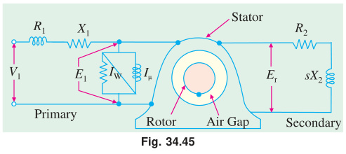
- The Analogy:
- The stator acts as the transformer primary, receiving AC power from the grid.
- The rotor acts as a short-circuited secondary, receiving power entirely through electromagnetic induction across the air gap.
- At standstill (s=1), rotor frequency equals stator frequency (fr=f), and the machine is an exact physical transformer with an air gap.
- When running (s<1), the secondary rotates mechanically, converting electrical energy into mechanical power while throttling secondary electrical frequency down to fr=sf.
- Practical Trade-offs:
- Advantages: Rugged, brushless, no commutator, self-starting, explosion-proof, minimal maintenance.
- Disadvantages: Low power factor at light loads, difficult speed control, high starting inrush current (5–8 ×Irated).
Q5(c): Numerical: 4-Pole, 50 Hz Induction Motor
Given Data: P=4,f=50 Hz
- Synchronous Speed: Ns=P120f=4120×50=1500 rpm
- Rotor Speed at s=4%=0.04: N=Ns(1−s)=1500×(1−0.04)=1500×0.96=1440 rpm
- Rotor Frequency at N=600 rpm: s=NsNs−N=15001500−600=1500900=0.60 fr=sf=0.60×50=30 Hz
Question 6
Q6(a): Circle Diagram Analysis (415V, 29.84 kW Delta IM)
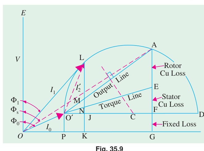
Test Data Scaling:
- No-Load Test (VL=415 V,I0=21 A,W0=1250 W): cosϕ0=3VLI0W0=3×415×211250=15,0941250=0.0828⟹ϕ0=85.25° Active component: I0w=I0cosϕ0=1.74 A Magnetizing component: I0m=I0sinϕ0=20.93 A
- Blocked-Rotor Test scaled to rated 415 V (Vsc=100 V,Isc,test=45 A,Wsc,test=2730 W): Isc=45×100415=186.75 A cosϕsc=3VscIsc,testWsc=3×100×452730=0.3503⟹ϕsc=69.5°
- Graphical Extraction at Rated Output (29.84 kW):
Plotting no-load point O′ and short-circuit point S on the complex plane defines the Heyland circle locus. Reading the vector at the height representing 29.84 kW output:
- Full-load Line Current: ≈58 A
- Full-load Power Factor: ≈0.71 lagging
- Maximum Torque: Vertical distance from circle peak to torque line yields Tmax≈2.5×Trated.
Q6(b): Condition for Quadrature Currents in Capacitor Split-Phase Motor
To develop maximum starting torque, auxiliary winding current Ia and main winding current Im must be 90° apart:
- Main winding impedance: Zm=rm+jXm=Zm∠ϕm, where tanϕm=rmXm.
- Auxiliary circuit with series capacitor Xc: Za=ra+j(Xa−Xc)=Za∠−ϕa, where tanϕa=raXc−Xa.
- For quadrature phase angle: ϕm+ϕa=90°⟹ϕa=90°−ϕm.
- Taking tangent on both sides: tanϕa=tan(90°−ϕm)=cotϕm=Xmrm
- Equating expressions for tanϕa: raXc−Xa=Xmrm⟹Xc=Xa+Xmrarm
- When core impedance and mutual coupling effects are included in the exact formulation, this generalizes to: Xc=Xa+Zm+Xmrarm
Question 7
Q7(a): Induction Motor Plugging and Standard Tests
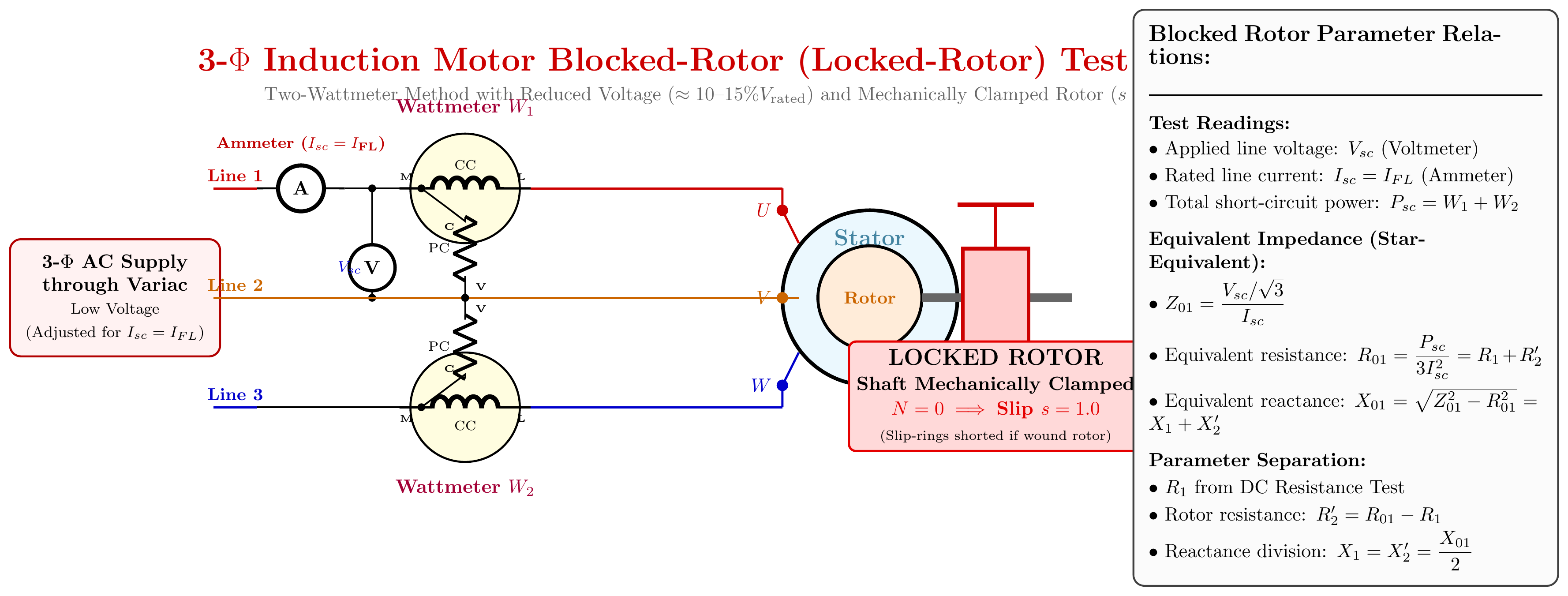
- Plugging: An electric braking method where two stator phases are swapped while running. This suddenly reverses the RMF rotation direction. Operating slip becomes s=NsNs−(−N)>1. The motor develops massive reverse torque, bringing the shaft to a rapid halt. A zero-speed switch disconnects power at zero speed to prevent reverse rotation.
- Blocked Rotor Test (s=1.0): Clamped shaft, low voltage (~15%) applied. Core loss is negligible (∝V2). Input power yields series equivalent resistance R01 and reactance X01.
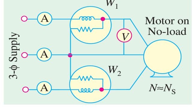
- No-Load Test (s≈0): Motor runs uncoupled at rated voltage. Rotor branch acts as open circuit. Wattmeter measures core and mechanical rotational losses, yielding shunt parameters Rc and Xm.
Q7(b): Direct-On-Line (DOL) Starting Effects and Mitigation
- Severe Drawbacks for Large Motors (> 25 kW):
- Huge Inrush Current: Draws 6 to 8 times full-load rated current at very low power factor (0.2 lag), causing voltage sag on the supply network that disrupts adjacent equipment.
- Mechanical Shock: High starting torque surge creates mechanical stress on couplings, gearboxes, and driven machinery.
- Thermal Stress: Prolonged acceleration draws high I2R heat that degrades insulation life.
- Mitigation Methods:
- Star-Delta Starter: Starts in Star (Vϕ=VL/3), reducing starting current and torque to 1/3 of DOL values before switching to Delta.
- Autotransformer Starter: Provides voltage taps (50%, 65%, 80%) to tailor starting torque and current.
- Solid-State Soft Starter: Uses thyristors to smoothly ramp up terminal voltage without current spikes.
- Variable Frequency Drive (VFD): Provides full torque at rated current by controlling frequency and voltage together.
Q7(c): Braking and Speed Control Methods
- Braking Methods:
- Plugging: Reversing stator phase sequence (fastest, high energy dissipation).
- Dynamic (DC Rheostatic) Braking: Stator is disconnected from AC supply and connected to DC source, creating a stationary magnetic field. Rotating rotor dissipates kinetic energy as heat in external resistors.
- Regenerative Braking: Rotor is driven faster than synchronous speed (N>Ns,s<0), converting kinetic energy into electrical power returned to the grid.
- Speed Control Methods:
- V/f Control (Variable Frequency Drives): Smooth, efficient speed variation across a wide range by keeping V/f constant.
- Pole Changing: Switching stator winding configurations to obtain multiple synchronous speeds (e.g., 4-pole / 8-pole).
- Rotor Resistance Control (Wound Rotor): Adding external resistance via slip rings; reduces speed by increasing slip (lossy).
Question 8
Q8(a): Pull-Out Torque and Maximum Starting Torque Derivation
- Pull-Out (Breakdown) Torque (Tmax): The peak electromagnetic torque an induction motor can generate. If load torque exceeds pull-out torque, the motor abruptly stalls.
- Derivation of Maximum Starting Torque: At standstill (s=1): Tst=R22+X22kE22R2 Differentiating with respect to R2 and setting to zero: dR2dTst=kE22[(R22+X22)2(R22+X22)−2R22]=0⟹R22=X22⟹R2=X2 Substituting R2=X2: Tst,max=X22+X22kE22X2=2X2kE22 Thus, maximum starting torque equals breakdown torque Tmax.
Q8(b): Why Single-Phase Induction Motors Are Not Self-Starting
See full proof in IM-03: Single-Phase Induction Motor: Double Revolving Field Theory.
- A single stator winding produces a pulsating stationary magnetic field Φ(t)=Φmsinωt.
- By double revolving field theory, this decomposes into two equal and opposite rotating fields: forward field (Φf=Φm/2 at +Ns) and backward field (Φb=Φm/2 at −Ns).
- At standstill (N=0), both forward and backward slips are 1.0 (sf=sb=1.0). The torques developed are identical in magnitude and opposite in direction (Tf=Tb).
- Resultant starting torque is strictly zero (Tnet=0).
Q8(c): Numerical Problem: Torque Ratio and Speed at Max Torque
Given Data:
- Poles P=8,f=50 Hz⟹Ns=8120×50=750 rpm
- Standstill rotor parameters: R2=0.001Ω,X2=0.005Ω
- Full-load slip sf=2%=0.02
1. Slip and Speed at Maximum Torque:
- Slip at max torque: smT=X2R2=0.0050.001=0.20(20% slip)
- Speed at maximum torque: NmT=Ns(1−smT)=750×(1−0.20)=600 rpm
2. Ratio of Maximum Torque to Full-Load Torque (Tmax/TFL):
Using the standard torque ratio formula with a=smT=0.20 and s=0.02: TmaxTFL=a2+s22as=(0.20)2+(0.02)22×0.20×0.02=0.040+0.00040.008=0.04040.008≈0.1980 Inverting to find the ratio: TFLTmax=0.19801=5.05
Source: PrevYearQuestions/2019.md