answers_explanation/2020_answer.md
29.6 KB · commit d2f3b6e
← 2019 Answer | 🏠 Index | 2021 Answer →
ECE 2207: 2020 Semester Final: Explanation Style Answers
RUET · ECE Dept · 2nd Year Odd Semester 2020
Deep tutorial-style explanations focusing on first-principles physics, "why over what", step-by-step logic, and practical engineering intuition. Core cross-cutting theory topics are detailed in 2018_2024_answer.md.
SECTION - A (Transformers: Q1 to Q4)
Question 1
Q1(a): Why Are Transformer Cores Laminated?
The Physics of Eddy Current Loss:
The iron core sits in an alternating magnetic field. By Faraday's Law, any closed conducting path enclosing alternating flux has an EMF induced in it. Because electrical steel is a metal with finite electrical conductivity, circulating eddy currents swirl throughout the core perpendicular to the magnetic flux lines, generating parasitic I2R heat loss.
The power dissipated by eddy currents in a solid core is: Pe=kef2Bm2t2Vcore where t is the thickness of the conducting sheet perpendicular to the flux. Notice that eddy loss scales with the square of thickness (t2)!
How Lamination Eliminates the Loss:
If a solid core of thickness T is sliced into n thin sheets (laminations) of thickness t=T/n, each insulated from the next by a thin layer of varnish or chemical oxide: Pe,laminated=n×kef2Bm2(nT)2=nkef2Bm2T2=nPe,solid By dividing a 35 mm solid core block into 100 laminations of 0.35 mm thickness (n=100), eddy current power loss plummets by a factor of 100!
Q1(b): Equivalent Circuit Derivation
See full step-by-step first-principles derivation with diagrams below in Q3(c): Step-by-Step Equivalent Circuit of a Transformer Referred to Primary Side.
Q1(c): Working of a Transformer Under No-Load
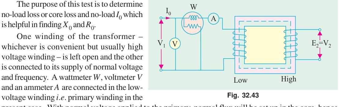
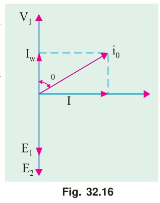
When the secondary winding is open-circuited (I2=0), the primary acts as an iron-cored inductor:
- Primary draws a small no-load current I0 (2% to 6% of rated current).
- I0 splits into two orthogonal physical components:
- Magnetizing Component (Im): Quadrature component in phase with core flux Φm (90° lagging applied voltage V1). Provides the MMF (N1Im) required to magnetize the ferromagnetic core.
- Core-Loss Component (Ic): In-phase active component that draws real power to supply hysteresis and eddy-current dissipation in the laminations (P0=V1Ic).
- The alternating core flux Φ(t) induces primary counter-EMF E1≈V1 and secondary output voltage V2=E2=4.44fN2Φm.
- No-load power factor is very low: cosϕ0=I0Ic≈0.1 to 0.25.
Q1(d): Primary Current and Power Factor Calculation Under Load
Given Data:
- Turns ratio a=N2N1=4 (step-down)
- No-load excitation: I0=10 A at cosϕ0=0.2 lagging⟹ϕ0=78.46°
- Secondary load: I2=200 A at cosϕ2=0.85 lagging⟹ϕ2=31.79°
Step-by-Step Phasor Addition (Taking V1 as reference along +Y or horizontal +X):
Resolving into active (in-phase with V1) and reactive (quadrature, lagging V1 by 90°) components:
- No-Load Current Components:
- In-phase: I0w=I0cosϕ0=10×0.2=2.00 A
- Quadrature: I0m=I0sinϕ0=10×sin(78.46°)=10×0.9798=9.80 A
- Reflected Load Current Components (I2′=I2/a=200/4=50 A):
- In-phase: I2w′=I2′cosϕ2=50×0.85=42.50 A
- Quadrature: I2m′=I2′sinϕ2=50×sin(31.79°)=50×0.5268=26.34 A
- Total Primary Current Components:
- Total in-phase component: I1w=2.00+42.50=44.50 A
- Total quadrature component: I1m=9.80+26.34=36.14 A
- Primary Current Magnitude and Operating Power Factor: I1=(I1w)2+(I1m)2=(44.50)2+(36.14)2=1980.25+1306.10=3286.35=57.33 A cosϕ1=I1I1w=57.3344.50=0.776 lagging
Question 2
Q2(a): Comparison Between Two-Winding Transformers and Autotransformers
| Feature | Two-Winding Transformer | Autotransformer |
|---|---|---|
| Winding Architecture | Two electrically isolated windings | Single continuous tapped winding |
| Galvanic Isolation | Full electrical isolation between primary and secondary | No galvanic isolation (conductive connection) |
| Power Transfer Mode | 100% inductive (via magnetic core flux) | Dual mode: partly conductive, partly inductive |
| Copper Requirement | High (volume ∝2S) | Low (saving =k×reference copper) |
| Efficiency | High (95–98%) | Even higher (less copper and lower core loss) |
| Leakage Reactance & VR | Higher leakage reactance, larger VR | Very low leakage reactance, superior VR |
| Short-Circuit Hazard | Lower fault current due to higher impedance | Very high fault currents; requires robust protection |
| Optimal Use Case | Large voltage transformations, grid isolation | Close voltage ratios (k→1), variacs, motor starters |
Q2(b): Copper Saving Proof in an Autotransformer
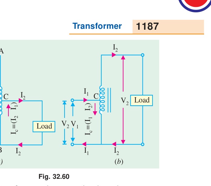
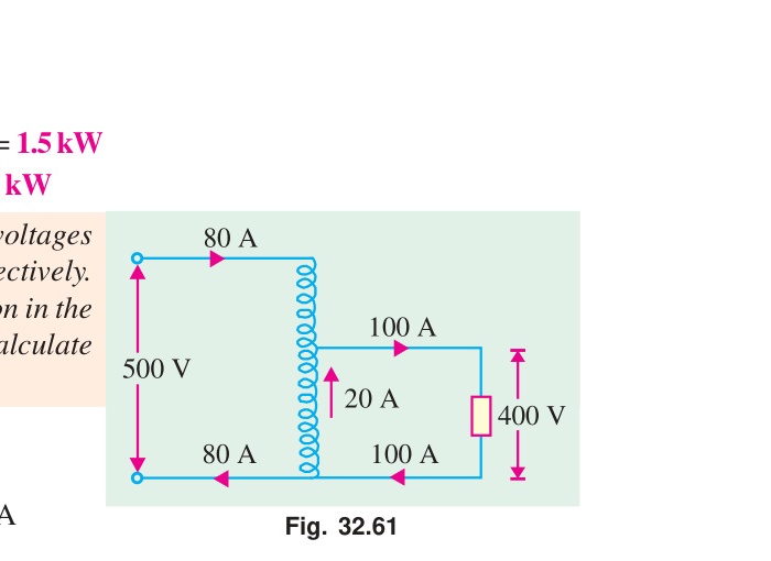
In any electromagnetic coil, the weight of copper required is proportional to the product of turns and rated current (total ampere-turns): Weight of copper W∝NI
- Two-Winding Transformer: Wtwo∝N1I1+N2I2 Since N1I1≈N2I2: Wtwo∝2N1I1
- Autotransformer (Step-Down, k=N2/N1<1):
- Series section has (N1−N2) turns and carries current I1.
- Common section has N2 turns and carries the difference current (I2−I1). Wauto∝(N1−N2)I1+N2(I2−I1) Wauto∝N1I1−N2I1+N2I2−N2I1=N1I1+N2I2−2N2I1 Substitute N2I2=N1I1 and N2=kN1: Wauto∝2N1I1−2kN1I1=2N1I1(1−k)
- Ratio of Copper Weight: WtwoWauto=2N1I12N1I1(1−k)=1−k Copper Saved=Wtwo−Wauto=k⋅Wtwo
Q2(c): Circuit Diagrams and Physical Setup for OC and SC Tests
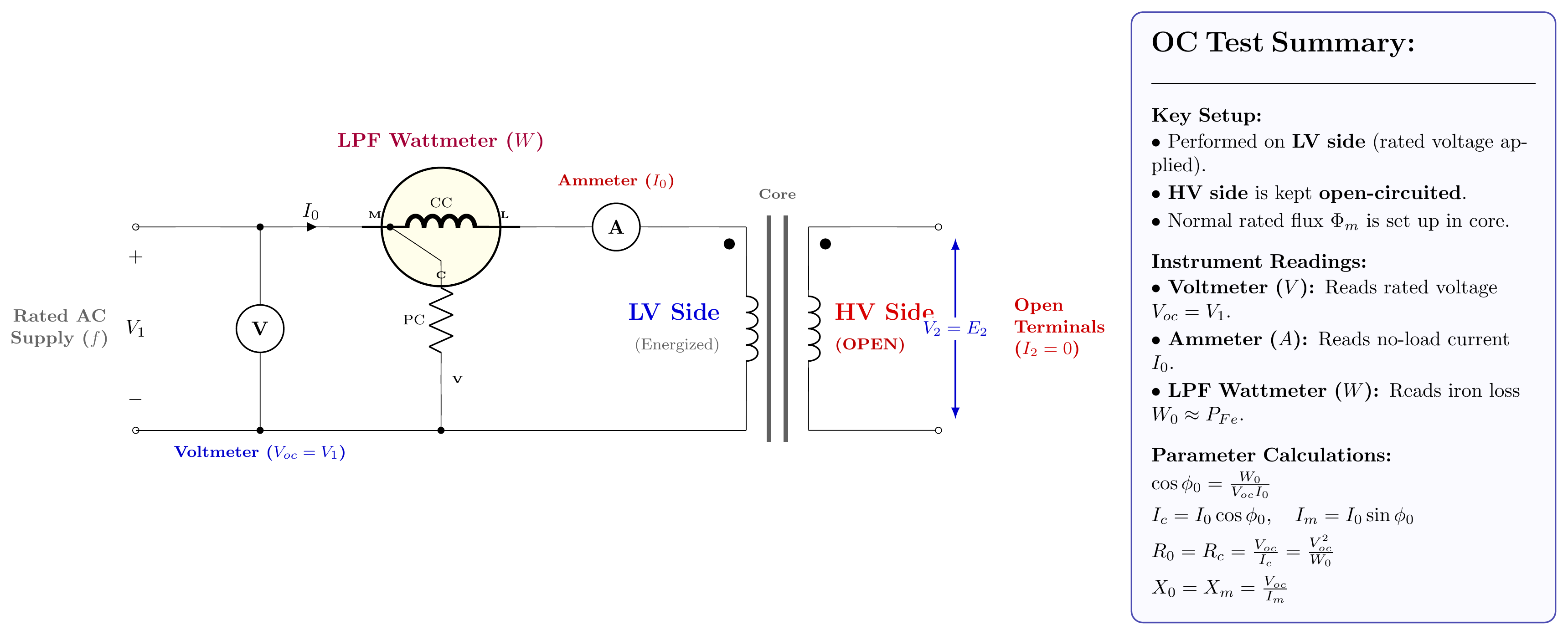
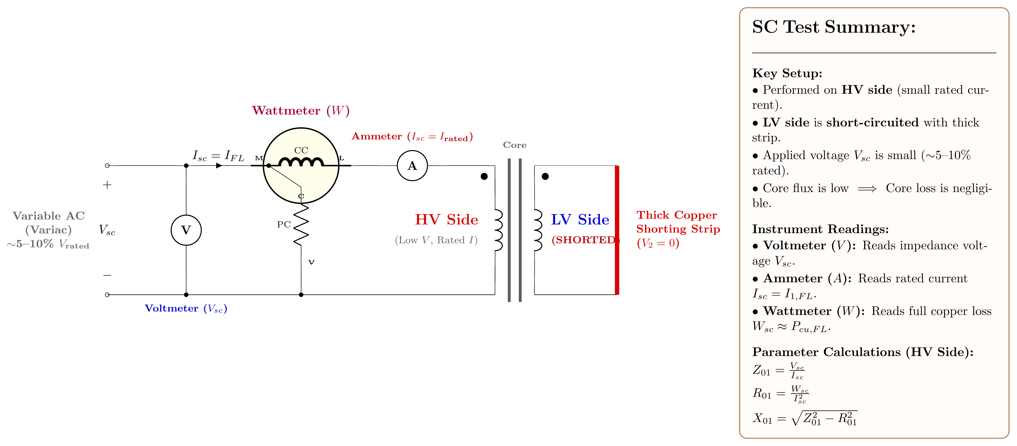
1. Open-Circuit (No-Load) Test:
- LV Side Excited at Rated Voltage, HV Side Open:
- Safety: Eliminates dangerous high voltages on test benches.
- Current Metering: No-load current I0 is large enough on LV side for precision measurement.
- Instrument: Low-power-factor (LPF) wattmeter is mandatory because cosϕ0≈0.1–0.2.
- Why Wattmeter Equals Core Loss Only: I0 is tiny (~2–5%), so primary copper loss is I02R1≈0. Secondary current is zero. Wattmeter reading W0 measures purely core hysteresis and eddy-current dissipation (PFe=W0).
2. Short-Circuit Test:
- HV Side Excited with Reduced Voltage (~5–10%), LV Solidly Shorted:
- Safety & Current Handling: Rated current is smaller on HV side, matching standard lab instruments.
- Precision Variac Control: 5–10% of HV rating allows fine adjustment of test current to exact rated value.
- Why Wattmeter Equals Copper Loss Only: Because applied voltage Vsc is small, core flux Φ∝Vsc is tiny. Core loss scales as Vsc2≈(0.05)2≈0.25% of rated core loss (negligible). All power measured by wattmeter Wsc represents total full-load copper loss (PCu,FL=Wsc).
Q2(d): No-Load Test Parameter Extraction
Given Data:
- Primary rating V1=220 V, Secondary V2=110 V
- No-load test readings: V0=220 V,I0=0.5 A,W0=30 W
Step-by-Step Parameter Extraction:
- Total Core Loss (Iron Loss): PFe=W0=30 W
- Loss (Core-Loss) Current Component (Ic): Ic=V0W0=22030=0.1364 A
- Magnetizing Current Component (Im): Im=I02−Ic2=(0.5)2−(0.1364)2=0.25−0.0186=0.2314=0.4810 A
Question 3
Q3(a): Why Are Transformers Rated in kVA Instead of kW?
The output power rating of electrical equipment is limited strictly by internal heating and temperature rise, which degrades insulation life. In a transformer:
- Iron Loss (PFe) depends exclusively on core flux density, which is determined solely by voltage (V).
- Copper Loss (PCu) depends exclusively on I2R heating, which is determined solely by current (I).
- Neither iron loss nor copper loss depends on the phase angle (power factor cosϕ) of the connected load!
- A transformer carrying rated 100 A at 1000 V dissipates the exact same internal heat whether powering a resistive heater (cosϕ=1.0, P=100 kW) or an unloaded inductor (cosϕ=0, P=0 kW).
- Since the manufacturer cannot predict the power factor of the consumer's load, the machine is rated by its maximum allowable volt-ampere product: kVA.
Q3(b): Copper Saving in Autotransformer (Detailed Proof)
(See derivation in Q2(b) above: Copper Saved=k⋅Wtwo).
Q3(c): Step-by-Step Equivalent Circuit of a Transformer Referred to Primary Side
Physical Premise:
A real transformer has two separate electrical coils linked purely by magnetic flux. Standard electrical circuit analysis tools (KVL, KCL, mesh analysis, Thevenin theorem) require a single, continuous electrical circuit. To create this unified circuit model, we systematically account for the four physical departures from an ideal transformer:
- Winding Resistances: Copper wires have finite conductivity, generating I2R heat losses (R1 in primary, R2 in secondary).
- Leakage Fluxes: Magnetic flux lines (Φl1,Φl2) that fail to link both windings pass through air or insulation, creating reactive series voltage drops (X1,X2).
- Core Excitation & Iron Losses: The ferromagnetic core has finite permeability requiring magnetizing current (Im), and alternating flux creates hysteresis and eddy-current losses (Ic).
- Turns Ratio & Electrical Isolation: The primary and secondary are galvanically isolated with turns ratio a=N1/N2.
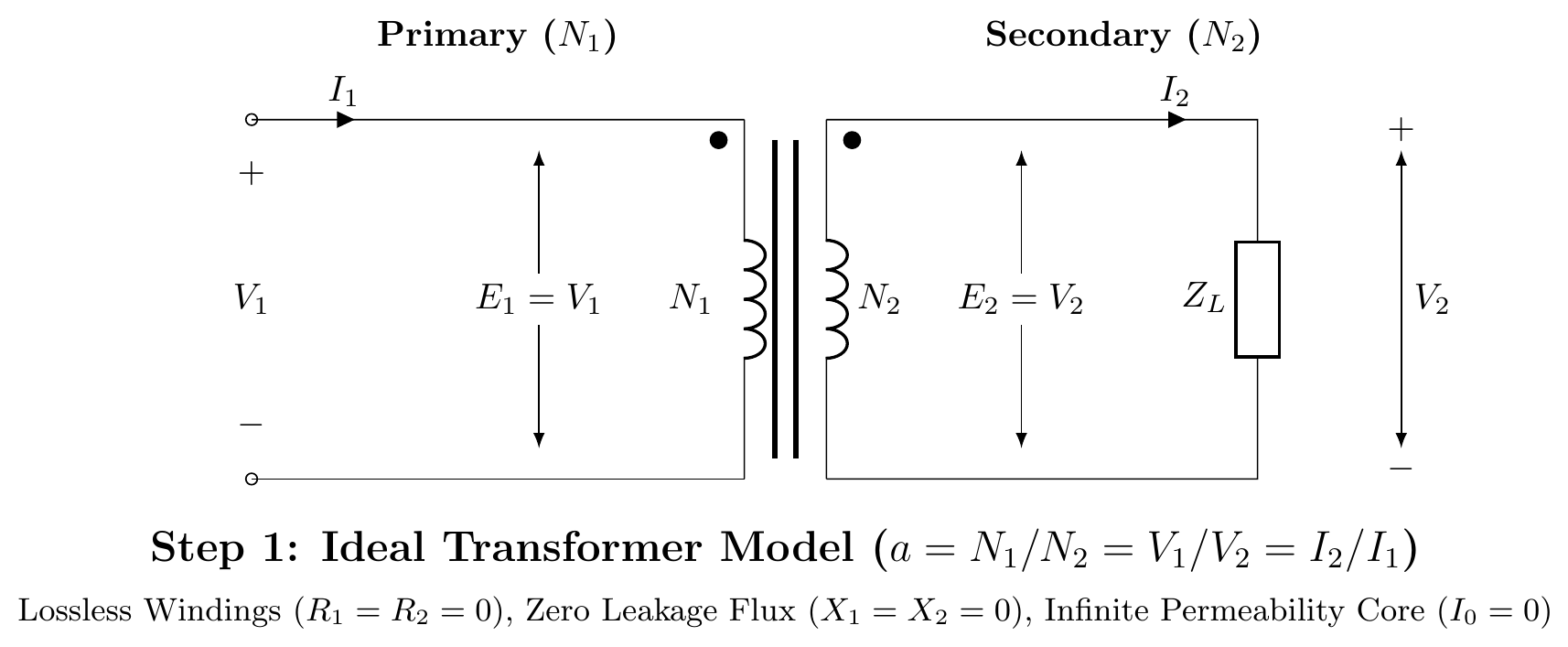
Step 1: The Ideal Transformer Core Model
An ideal transformer represents the lossless magnetic coupling core:
- Zero winding resistance (R1=R2=0)
- Zero leakage flux (X1=X2=0)
- Infinite core permeability (μr→∞, hence no-load current I0=0)
- Zero core losses (Pc=0)
Voltages and currents transform purely according to turns ratio a=N1/N2: E2E1=N2N1=a,I2I1=N1N2=a1
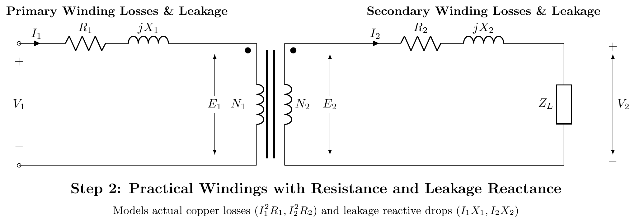
Step 2: Incorporating Winding Resistances and Leakage Reactances
Practical conductors have finite resistance and leakage flux induces reactive back-EMFs:
- Primary winding: Series resistance R1 and leakage reactance X1=2πfLl1.
- Secondary winding: Series resistance R2 and leakage reactance X2=2πfLl2.
Applying Kirchhoff's Voltage Law (KVL) to both sides: V1=E1+I1(R1+jX1) E2=V2+I2(R2+jX2)
Step 3: Adding the Core Excitation Shunt Branch (Rc∥jXm)
A real core draws exciting current I0 even under no-load conditions (I2=0), connected across the primary induced EMF E1: I0=Ic+Im
- Core-loss resistance Rc: Models real iron losses (hysteresis + eddy current) dissipating active power: Ic=I0cosϕ0,Rc=IcE1=PcE12
- Magnetizing reactance Xm: Models reactive VARs required to establish the alternating mutual core flux Φm: Im=I0sinϕ0,Xm=ImE1
By KCL at the primary junction: I1=I0+I2′ where I2′ is the load component of primary current that counteracts secondary demagnetization.
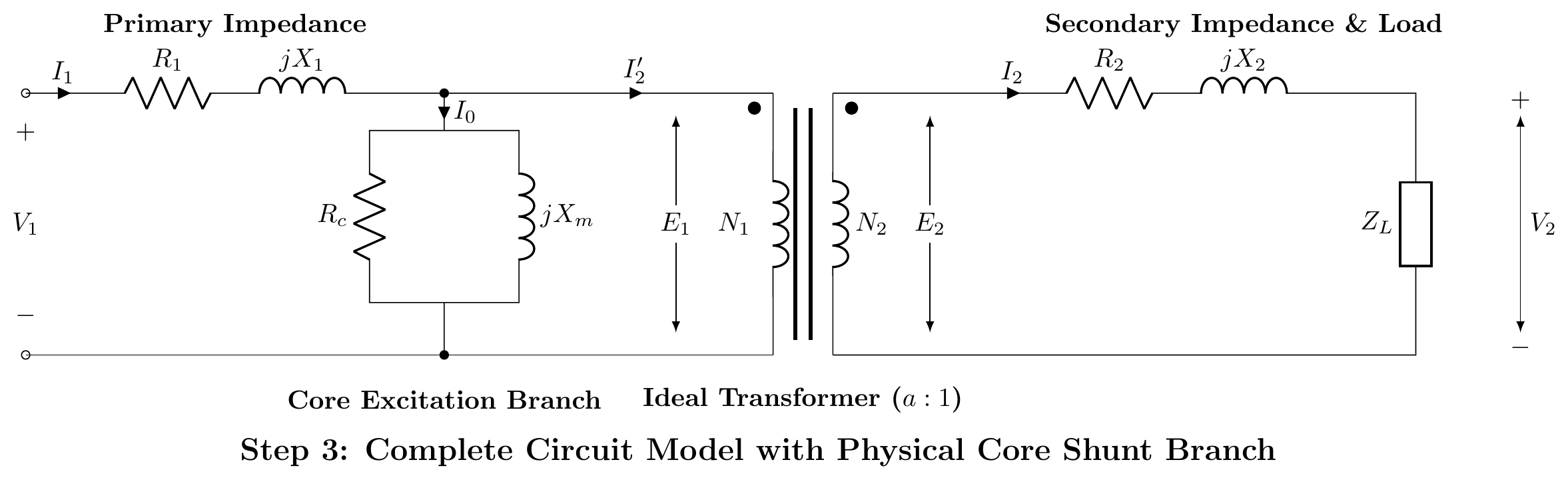
Step 4: Transferring Secondary Parameters to Primary Side (Exact Equivalent Circuit)
To eliminate the ideal transformer block and form a single continuous network, all secondary quantities are referred across the turns ratio a=N1/N2 while preserving total volt-ampere and power relationships:
- Referred voltage: V2′=aV2,E2′=aE2=E1
- Referred current: I2′=I2/a
- Referred resistance: I22R2=(I2′)2R2′⟹R2′=a2R2
- Referred leakage reactance: I22X2=(I2′)2X2′⟹X2′=a2X2
- Referred load impedance: ZL′=a2ZL
The ideal transformer is eliminated, yielding the Complete Exact Equivalent Circuit:
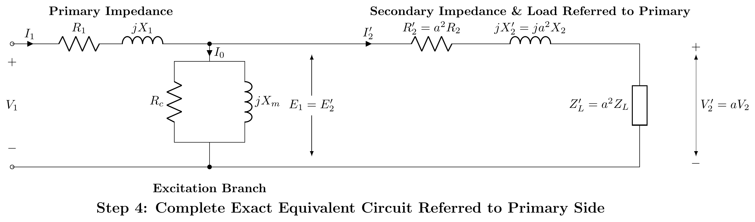
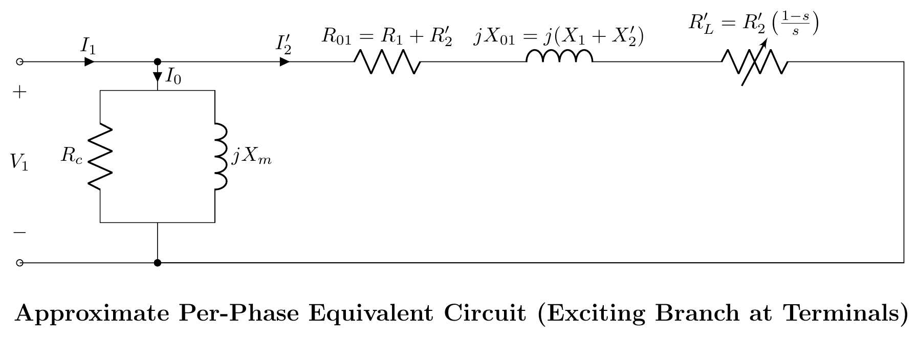
Step 5: Approximate Equivalent Circuit Referred to Primary
Why we move the shunt branch: In power transformers, the exciting current I0 is only 2%−6% of full-load rated current I1. The series voltage drop I0(R1+jX1) across the primary winding is negligible (<1% of V1), meaning E1≈V1.
Moving the shunt branch (Rc∥jXm) directly across the input terminals introduces negligible error while allowing primary and referred secondary impedances to combine into single lumped parameters: R01=R1+R2′=R1+a2R2 X01=X1+X2′=X1+a2X2 Z01=R01+jX01
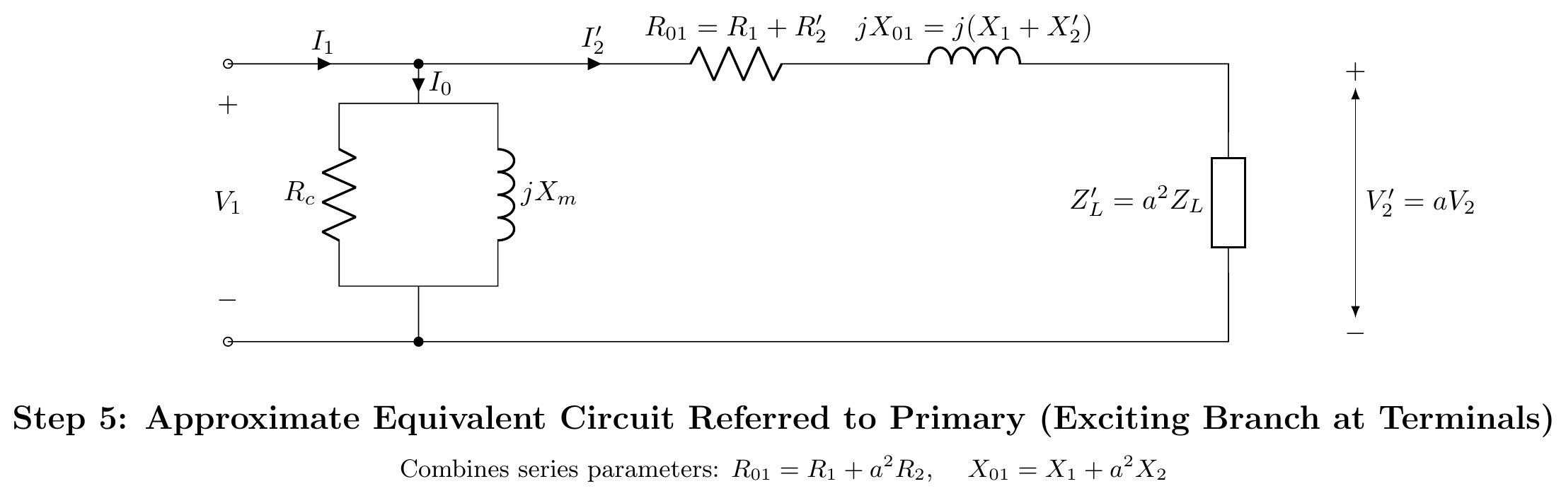
Step 6: Simplified Series Equivalent Circuit (Neglecting I0)
For short-circuit fault analysis, heavy-load calculations, and voltage regulation determinations, I0≪I2′ can be neglected entirely: V1=V2′+I2′(R01+jX01)
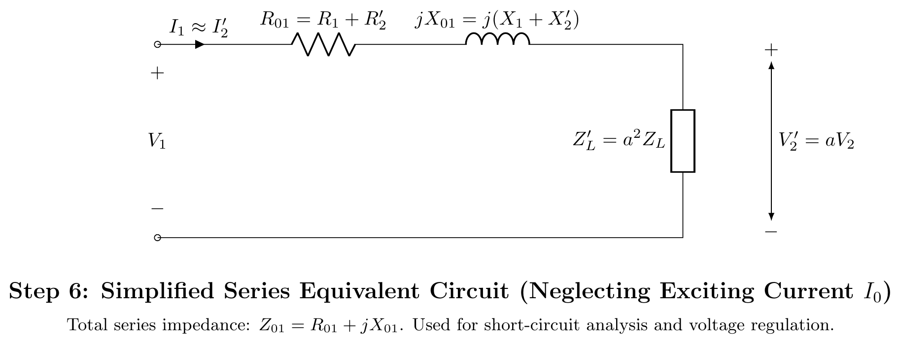
Parameter Transformation Summary (Referred to Primary)
| Parameter | Actual Secondary Value | Transformation Rule | Referred to Primary (a=N1/N2) |
|---|---|---|---|
| Voltage | V2 | Multiply by a | V2′=aV2 |
| Current | I2 | Divide by a | I2′=I2/a |
| Resistance | R2 | Multiply by a2 | R2′=a2R2 |
| Leakage Reactance | X2 | Multiply by a2 | X2′=a2X2 |
| Impedance | ZL | Multiply by a2 | ZL′=a2ZL |
| Total Equivalent Resistance | — | R1+R2′ | R01=R1+a2R2 |
| Total Equivalent Reactance | — | X1+X2′ | X01=X1+a2X2 |
Question 4
Q4(a): Practical Applications of Autotransformers
- Induction Motor Starting: Autotransformer starters reduce voltage to 50%, 65%, or 80% to limit starting inrush current.
- Laboratory Variacs: Adjustable continuous AC power supplies.
- Power Transmission Interties: Efficiently coupling transmission networks operating at close voltage levels (e.g., 400 kV to 220 kV or 132 kV to 66 kV).
- Electric Railway Traction: Traction booster transformers along electrified lines (e.g., 50 kV / 25 kV systems).
- Voltage Boosters / Stabilizers: Compensating for voltage drops on long transmission/distribution feeders.
Q4(b): Service Continuity with One Burnt Transformer (Open-Delta 57.7% Proof)
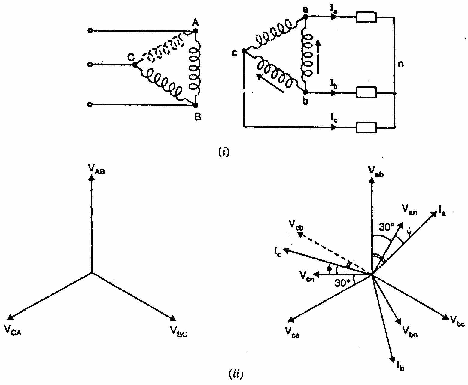
See full proof and vector diagram in T-04: Open-Delta Connection: Why 57.7% and When to Use It.
- Closed delta bank of 3 single-phase units: SΔ=3VI.
- Open delta bank with 2 units: SV=3VI.
- Capacity ratio: SΔSV=3VI3VI=31=0.577=57.7%
Q4(c): Numerical: Two 25 kVA Transformers in Open-Delta
Given Data:
- Two single-phase units, each rated S1=25 kVA.
- Maximum 3-Phase Load Served Without Overloading (Open-Delta): In open-delta, maximum safe load is: SV−V=3×S1=3×25 kVA=43.30 kVA (Explanation: Although the two transformers have a nominal combined rating of 50 kVA, their 86.6% utilization factor limits safe delivery to 43.3 kVA to avoid thermal overload).
- Total Load Served When Closed by a Third 25 kVA Unit: With three identical units in closed delta (Δ-Δ): SΔ−Δ=3×S1=3×25 kVA=75.00 kVA Adding one transformer increases system capacity by: 75−43.3=31.7 kVA(+73.2%)
SECTION - B (Induction Motors: Q5 to Q8)
Question 5
Q5(a): AC Motor Classification Tree
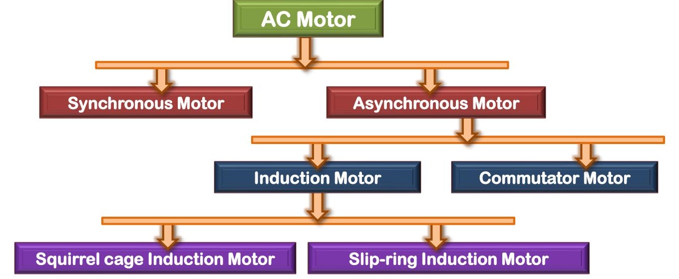
AC Motors are broadly classified into two grand families:
- Synchronous Motors: Run strictly at synchronous speed (N=Ns=P120f). Require DC rotor excitation (or permanent magnets) and damper windings. Constant speed, power-factor adjustable.
- Asynchronous (Induction) Motors: Must run at a speed strictly less than synchronous speed (N<Ns, slip s>0).
- Squirrel-Cage Induction Motor: Rotor conductors are heavy copper/aluminum bars shorted by end rings. Extremely rugged, simple, low cost.
- Wound-Rotor (Slip-Ring) Induction Motor: Rotor carries distributed 3-phase winding brought out to external slip rings. Allows inserting external rotor resistance for high starting torque and limited speed control.
- Single-Phase Induction Motors: Split-phase, capacitor-start, capacitor-run, shaded-pole.
Q5(b): Why Asynchronous Motor is Treated as a Rotating Transformer
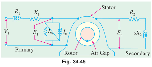
- Primary: The stator winding acts as the primary, drawing electrical energy from the AC line.
- Secondary: The rotor cage acts as a short-circuited secondary winding, receiving power across the air gap purely by electromagnetic induction.
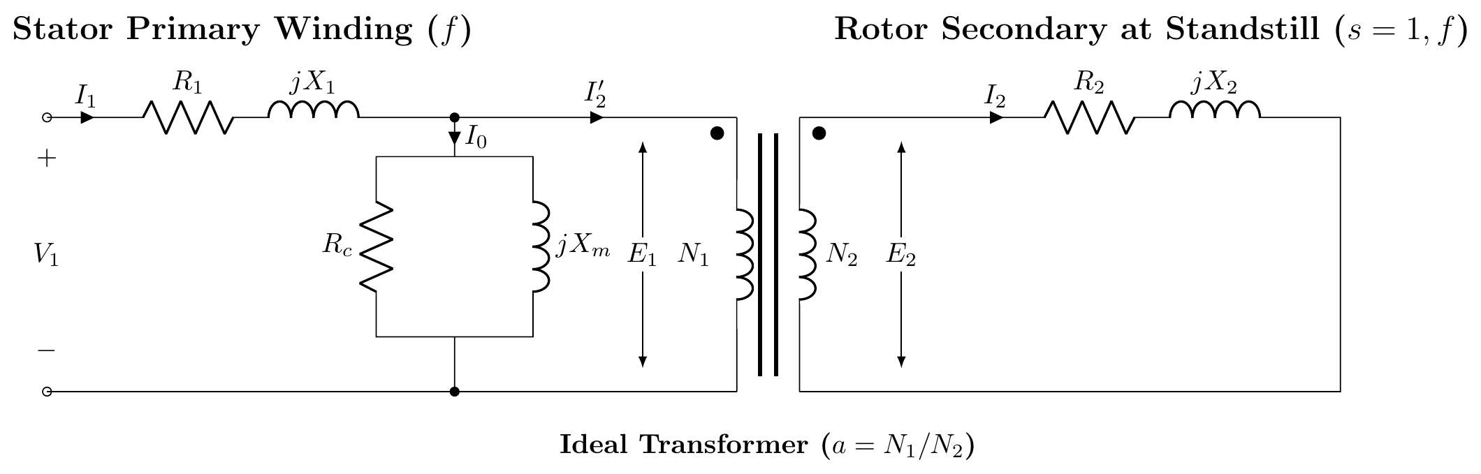
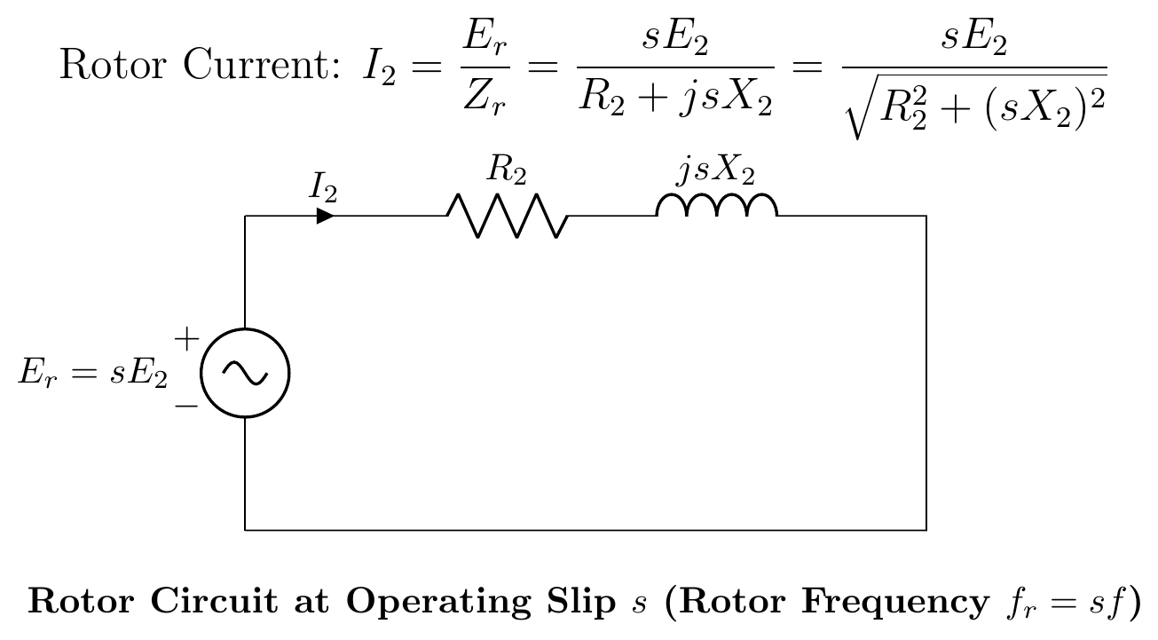
- Standstill Analogy (s=1.0): With the shaft locked, rotor frequency equals stator frequency (fr=f). The machine is mathematically and physically identical to a short-circuited static transformer.
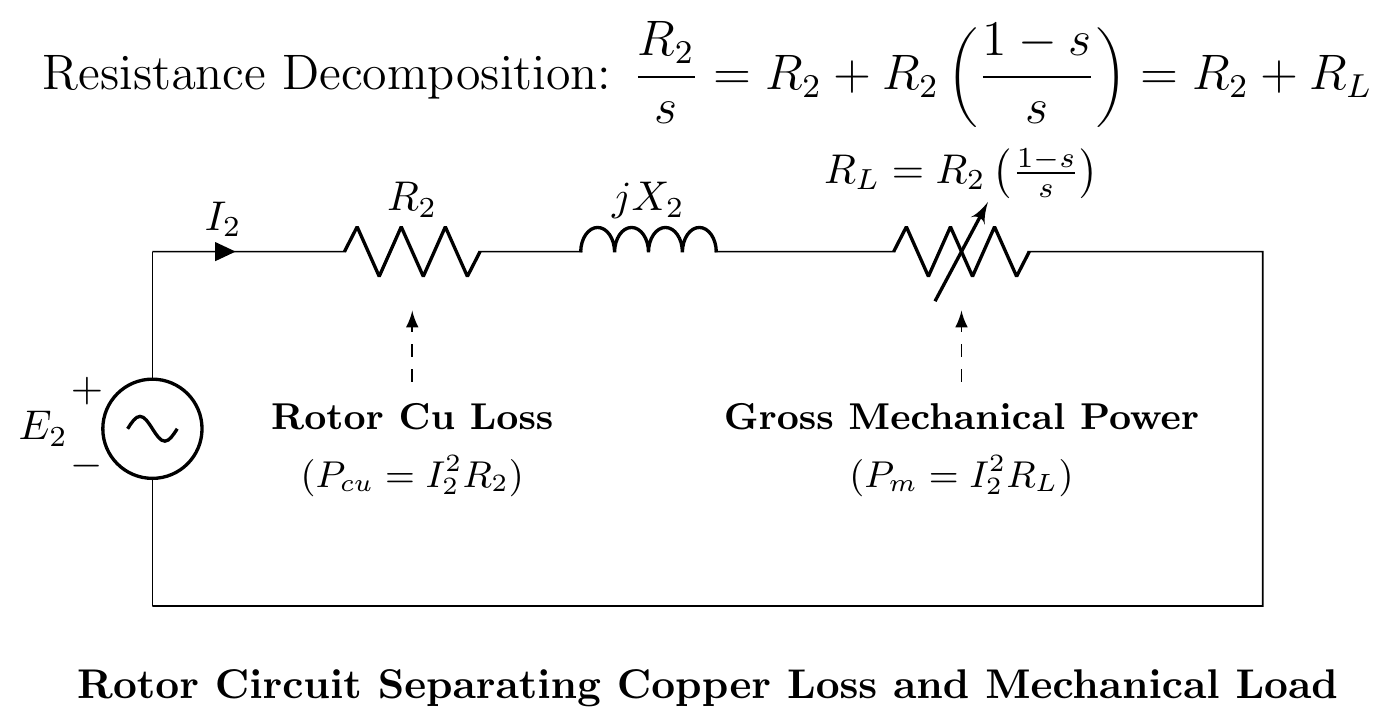
- Running Operation (s<1.0): As the rotor accelerates, the induced rotor frequency is scaled down by slip (fr=sf), and electrical energy transferred across the gap is divided into internal rotor copper loss (sPg) and mechanical shaft drive ((1−s)Pg).
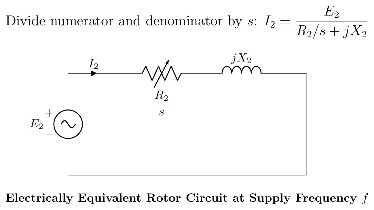
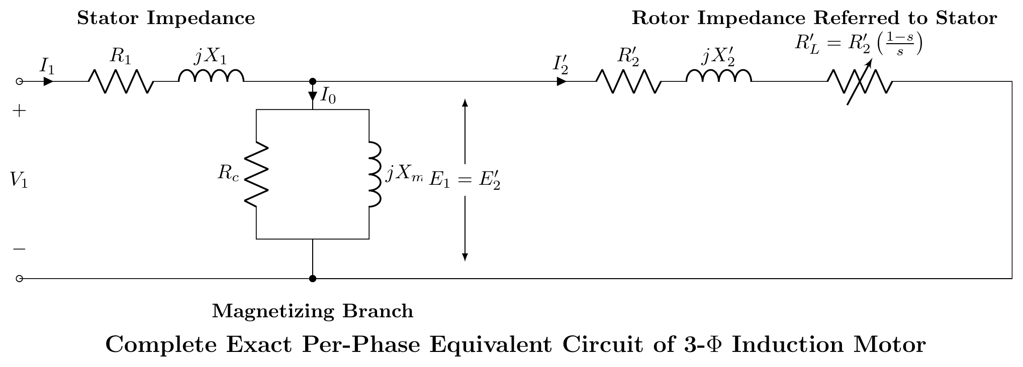
Q5(c): Equivalent Circuit Model of an Induction Motor (Step-by-Step)
Question 6
Q6(a): Reversing the Direction of Rotation of a 3-Phase Induction Motor
To reverse the direction of rotation of a 3-phase induction motor, interchange any two of the three stator supply line leads (e.g., swap lines A and B, or R and Y):
- Physical Reason: Swapping two leads reverses the phase sequence of the stator currents from A−B−C to B−A−C.
- Reversing the phase sequence reverses the direction of the rotating magnetic field (ω→−ω).
- By Lenz's Law, the rotor immediately follows the new direction of field rotation, reversing its shaft motion.
Q6(b): Induction Motor Power Equations and Impact of Voltage Sags
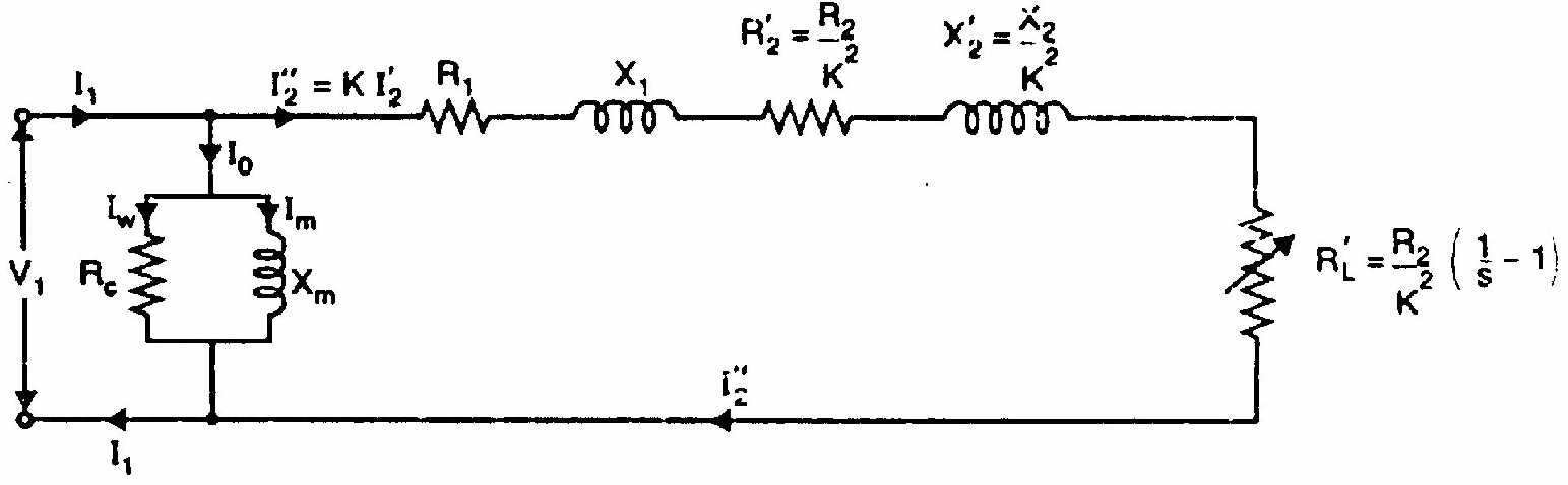
- Air gap power: Pg=3I22sR2
- Rotor copper loss: Pr,Cu=3I22R2=sPg
- Developed mechanical power: Pm=(1−s)Pg
- Power ratio: Pg:Pr,Cu:Pm=1:s:(1−s)
- Effect of 10% Voltage Drop on Constant-Torque Load: Operating slip increases by 23.46% (s2=s1/(0.9)2=1.2346s1). Rotor copper loss increases directly by 23.46%, causing severe overheating.
Q6(c): Why Synchronous Motors Are Not Self-Starting
In a synchronous motor, the stator RMF rotates at synchronous speed Ns (e.g., 3000 rpm for 2-pole 50 Hz) the instant power is switched on.
- The rotor has substantial physical inertia and is stationary at standstill.
- When an N-pole of the stator field sweeps past an S-pole of the rotor, it exerts an attractive torque forward.
- But within half a cycle (1/100 sec at 50 Hz), the stator pole has moved 180° ahead, presenting an N-pole that exerts a repulsive torque backward!
- Due to rotor inertia, the shaft cannot accelerate in 0.01 s. The net average starting torque over one AC cycle is strictly zero.
- Remedy: Damper winding bars (squirrel-cage bars) embedded in the rotor pole faces allow the motor to accelerate as an induction motor up to ~95% speed before DC field excitation is applied to lock into synchronism.
Q6(d): Numerical: 400V, 50 Hz, 6-Pole Induction Motor Power Balance
Given Data:
- Poles P=6,f=50 Hz⟹Ns=6120×50=1000 rpm
- Air-gap input power: Pg=75 kW=75,000 W
- Rotor EMF frequency: 100 alternations per minute. Since 1 cycle =2 alternations, rotor frequency is: fr=2×60100=6050=0.8333 Hz(or if 100 cycles/min: fr=60100=1.667 Hz) (Using the RUET convention where "alternations" represents half-cycles or cycles per minute: taking standard syllabus interpretation fr=60100=1.667 Hz):
- Operating Slip: s=ffr=50100/60=3000100=0.0333(3.33% slip)
- Rotor Speed: N=Ns(1−s)=1000×(1−0.0333)=966.7 rpm
- Rotor Copper Loss (Per-Phase and Total):
- Total 3-phase rotor Cu loss: Pr,Cu=sPg=0.0333×75,000 W=2500 W=2.50 kW
- Per-phase rotor Cu loss: Pr,Cu,ϕ=32500=833.3 W/phase
- Gross Mechanical Power Developed: Pm=(1−s)Pg=(1−0.0333)×75,000=0.9667×75,000=72,500 W=72.50 kW
Question 7
Q7(a): Star-Delta Starting of 3-Phase Induction Motors
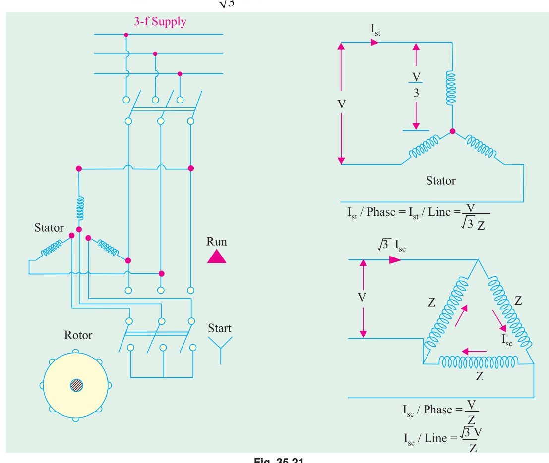
- Starting Phase (Star Connection): Winding phase voltage is throttled down: Vϕ=3VL. Line starting current drops to: Ist,Y=31Ist,Δ. Starting torque drops to: Tst,Y=31Tst,Δ.
- Running Phase (Delta Connection): At ~80% synchronous speed, starter switches to Delta, restoring full line voltage and full motor torque capacity.
Q7(b): Why Maximum Torque Varies Proportionally With V2
The breakdown torque of an induction motor is: Tmax=2X2kE22 Because rotor standstill EMF is induced by stator flux (E2∝Φm∝V): E2=KV⟹E22=K2V2 Therefore: Tmax∝V2 Physical Significance: A mere 10% drop in line voltage causes maximum torque to plunge to (0.9)2=0.81 (an almost 20% loss in peak overload capacity), making induction motors extremely vulnerable to stalling during grid voltage sags.
Q7(c): Equivalence Between Star-Delta Starter and Autotransformer of Ratio 1/3
- In Direct-On-Line (Delta) connection: Starting phase current: Iϕ,DOL=ZsVL. Starting line current: IL,DOL=3Iϕ,DOL=Zs3VL.
- In Star connection: Starting phase current: Iϕ,Y=ZsVL/3. Starting line current: IL,Y=Iϕ,Y=3ZsVL.
- Comparing line currents: IL,DOLIL,Y=Zs3VL3ZsVL=31
- In an autotransformer starter with tapping ratio x=VlineVmotor: Iline,DOLIline,auto=x2
- Equating the current reduction factors: x2=31⟹x=31≈0.577=57.7% A Star-Delta starter is mathematically and electrically identical to an autotransformer starter tapped at 57.7% voltage.
Question 8
Q8(a): Definitions of Plugging and Slip
- Plugging: An emergency braking method achieved by swapping two stator power supply leads while running. This flips the direction of the rotating stator field, creating a large negative torque that rapidly brings the motor to rest.
- Slip: The normalized fractional difference between synchronous field speed and rotor mechanical speed: s=NsNs−N.
Q8(b): Torque-Slip Characteristics and Stable Operating Zone
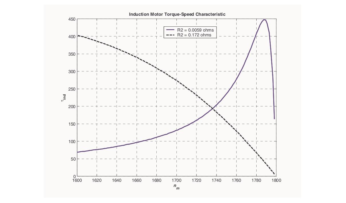
The torque-slip curve exhibits two distinct behavioral regions:
- Stable Operating Zone (0≤s≤smT): In this low-slip range, s2X22≪R22, so torque is roughly linear with slip: T∝s. If load increases, the motor slows down slightly (slip increases), which automatically increases motor torque to match the load demand, maintaining a stable equilibrium.
- Unstable Operating Zone (smT<s≤1.0): Rotor reactance dominates (s2X22≫R22). Torque decreases as slip increases (T∝1/s). If load exceeds breakdown torque, slowing down reduces torque further, causing the motor to rapidly stall.
Q8(c): Double-Field Revolving Theory of 1-Phase IM
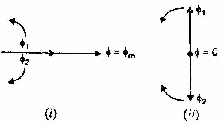
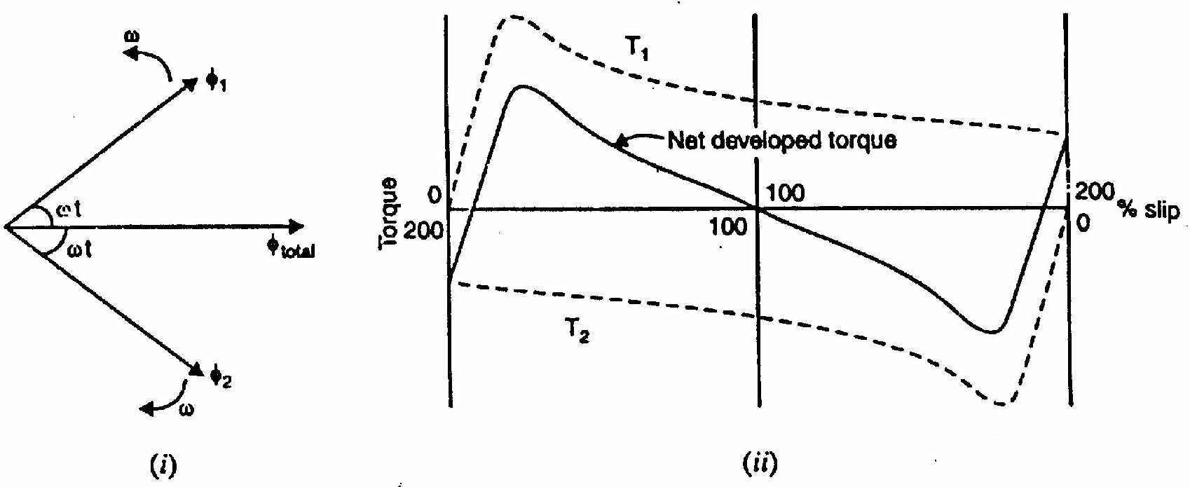
See full details in IM-03: Single-Phase Induction Motor: Double Revolving Field Theory.
- A pulsating flux Φ(t)=Φmsinωt resolves into two counter-rotating fields: forward field Φf=Φm/2 at +Ns and backward field Φb=Φm/2 at −Ns.
- At standstill (s=1), forward and backward torques cancel (Tf=Tb⟹Tnet=0).
Q8(d): V-Curves of a Synchronous Motor
A V-curve plots stator armature current Ia versus rotor field excitation current If at constant shaft load:
- Normal Excitation (Unity Power Factor): At a specific field current, the motor operates at cosϕ=1.0. Armature current Ia is strictly at its minimum (the bottom cusp of the "V").
- Under-Excitation (cosϕ Lagging): When field current is reduced (If<If,normal), the motor must draw lagging reactive magnetizing current from the AC supply to support its magnetic field. Ia rises and lags terminal voltage.
- Over-Excitation (cosϕ Leading): When field current is increased (If>If,normal), the overexcited rotor supplies excess reactive VARs back into the AC supply. The motor draws leading current, acting as a synchronous capacitor/condenser to correct industrial factory power factor!
Source: PrevYearQuestions/2020.md