answers_explanation/2018_2024_answer.md
28.2 KB · commit d2f3b6e
← 2024 Answer | 🏠 Index | (end)
ECE 2207: 2018–2024 Semester Finals: Explanation Style Answers
ECE 2207: Electrical Machines I | RUET
How to use this file: Deep explanations for the most important and frequently repeated questions from 2018–2024. These answers explain why: the physics, the logic, the intuition behind each concept. They complement the concise exam-style answers in
answers_exam_style/.
Transformer Topics (2018–2024)
T-01: EMF Equation: E=4.44fNΦm: Full Derivation and Intuition
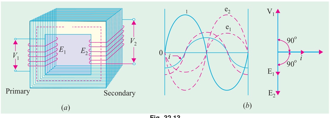
Appears in: 2019 Q1b, 2021 Q1b, 2023 Q1b, 2024 Q4a, CT-03 Q2
Why the EMF equation matters
This equation is the fundamental design equation of every transformer, every motor, every generator. If you know the supply voltage, frequency, and how many turns you want to use, this equation tells you how much core flux you need, or how big the core cross-section must be.
Physical picture before the math
Imagine threading a loop of wire through a magnetic core. If the flux through that core changes, an EMF appears in the wire (Faraday's Law). The faster the flux changes, the bigger the EMF.
For an AC supply at frequency f, the flux changes from peak to zero in quarter of a cycle: a time of T/4=1/(4f) seconds. The faster the frequency, the less time to change, the bigger the average rate of change, the bigger the average EMF.
This is why f appears in the formula.
The two-step derivation
Step 1: Write the flux waveform.
The core of an ideal transformer operating from a sinusoidal supply carries a sinusoidal flux: Φ(t)=Φmsin(ωt)=Φmsin(2πft)
Here Φm is the peak value in webers (Wb), f is frequency in Hz.
Step 2: Apply Faraday's Law.
For a winding of N1 turns linking the core flux, the induced EMF is: e1(t)=−N1dtdΦ
Differentiate: dtdΦ=Φm⋅ωcos(ωt)
So: e1(t)=−N1ωΦmcos(ωt)
Writing −cosθ=sin(θ−90°): e1(t)=N1ωΦmsin(ωt−90°)
This tells us two things:
- The induced EMF is also sinusoidal.
- It lags the core flux by exactly 90°. (The flux reaches its peak when the rate of change is zero, so EMF is zero at that instant, and the EMF is maximum when flux passes through zero: i.e., 90° behind.)
Step 3: Find the RMS value.
The peak value of the primary EMF: Em1=N1ωΦm=N1⋅2πf⋅Φm
For a pure sine wave, RMS = peak / 2: E1=2Em1=22πfN1Φm=22πfN1Φm=2πfN1Φm
Step 4: Compute the numerical constant. 2π=1.41421×3.14159=4.44288≈4.44
E1=4.44fN1Φm
For the secondary: The identical flux Φ(t) threads through all N2 secondary turns (no leakage assumed). By the same derivation: E2=4.44fN2Φm
Alternative derivation using average EMF
In the first quarter-cycle (time =T/4=1/(4f)), the flux rises from 0 to Φm:
Average rate of change of flux=1/(4f)Φm−0=4fΦm Wb/s
By Faraday's Law, average EMF per turn =4fΦm V.
For a sine wave, the form factor (ratio of RMS to average full-wave rectified value) is: Kf=AverageRMS=22π=1.1107≈1.11
RMS EMF per turn =1.11×4fΦm=4.44fΦm
Multiply by turns: E1=4.44fN1Φm,E2=4.44fN2Φm✓
What the formula tells the transformer designer
From E1=4.44fN1Φm and V1≈E1: Φm=4.44fN1V1
If core cross-section is A m², then Bm=Φm/A.
Design implication: For a given supply voltage and frequency, the peak flux density Bm determines N1, and then N2=N1×V2/V1. The core area A is chosen so that Bm<Bsaturation (~1.5–1.8 T for silicon steel).
Sources: Books/Ch-32_01_Construction_and_Principles.md · ClassNoteByRaidah/Class_13.md · SlidesByMaam/L-02_ECE-2207.md · Ankit_Goyal_YT_Playlist
T-02: Leakage Flux: Physical Picture and All Effects
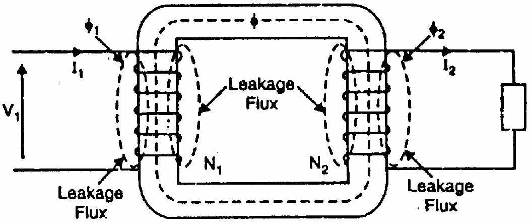
Appears in: 2024 Q2b, CT-04 Q1
The ideal vs. real transformer
In an ideal transformer, every magnetic flux line stays inside the iron core and links both primary and secondary windings. In reality, some flux takes a shortcut through the surrounding air or insulation without completing the path through the core.
This "straying" flux is called leakage flux. It is the single most important non-ideality of a transformer that affects its voltage regulation and equivalent circuit.
Three categories of flux
Mutual flux Φm: Travels through the core and links both windings. This is the useful flux: the one that transfers power from primary to secondary. Without it, no transformation happens.
Primary leakage flux Φl1: Created by primary current I1. Instead of going through the secondary core window, it bulges out through the air surrounding the primary coil, then returns. It links primary turns only.
Secondary leakage flux Φl2: Created by secondary current I2. Similarly leaks through air around the secondary coil, linking only the secondary turns.
Why does leakage flux travel through air?
The air path has constant (and low) magnetic permeability, unlike the iron core whose permeability is thousands of times higher. But even with low permeability, the air path near the windings is very short. The total reluctance of the leakage path can still be low enough to carry a small fraction of the total flux.
Since air doesn't saturate, leakage flux is directly proportional to current: Φl1=Ll1I1/N1∝I1
This is a linear relationship: leakage flux waveform is exactly in phase with the current causing it.
Effect 1: Leakage EMFs and Leakage Reactance
The alternating leakage flux Φl1 induces an EMF in the primary by Faraday's Law: el1=−N1dtdΦl1
Since Φl1∝I1 and the current is sinusoidal, the leakage flux is also sinusoidal and in phase with I1. The derivative dΦl1/dt is 90° ahead of Φl1. So the leakage EMF lags the current by 90°.
An EMF that lags the driving current by 90° behaves exactly like the voltage drop across an inductor. So we model the primary leakage as a series inductive reactance: X1=ωLl1=2πfLl1
This reactance limits the primary current and causes a voltage drop. Similarly for the secondary: X2=ωLl2=2πfLl2
Effect 2: Series voltage drops
The terminal voltage equations become:
Primary (applying KVL): V1=E1+I1R1+jI1X1
The applied voltage must overcome the back-EMF (E1), the resistive drop (I1R1), and the reactive drop (jI1X1).
Secondary (applying KVL): V2=E2−I2R2−jI2X2
The secondary terminal voltage is less than E2 because of drops across R2 and X2 inside the winding.
Effect 3: Worsened voltage regulation
Voltage regulation (VR) measures how much the secondary voltage drops from no-load to full-load.
At no-load: I2=0, no drops, V2=E2.
At full-load with lagging power factor: both the resistive drop I2R2 and the reactive drop I2X2 pull V2 below E2.
For lagging loads, the reactive drop subtracts from E2: ∣V2∣≈E2−I2(R2cosϕ+X2sinϕ)
The leakage reactance X2 contributes significantly to poor regulation for inductive loads.
For leading loads (capacitive), the reactive drop can add back (negative regulation: voltage actually rises with load), which is beneficial.
Effect 4: Fault current limiting: a benefit
During a secondary short circuit, the only impedance limiting the fault current is Z01=R012+X012 (total leakage impedance referred to primary).
Without leakage reactance, short-circuit current would approach infinity. Leakage reactance physically limits the fault current to about 5–10 times rated current in well-designed power transformers. This prevents mechanical and thermal destruction during faults.
Sources: Books/Ch-32_02_Equivalent_Circuit_and_Drop.md · ClassNoteByRaidah/Class_14.md · SlidesByMaam/L-06_ECE-2107.md
T-03: Efficiency and All-Day Efficiency
Appears in: 2018 Q2, 2019 Q4c, 2020 Q3, 2021 Q2, 2023 Q2a
Understanding the loss model
A transformer has two types of losses:
Iron (core) loss PFe: Consists of eddy current loss and hysteresis loss. Both depend on flux density in the core. Since B∝V/f, and the supply voltage is nearly constant, iron loss is essentially constant at all loads. Even at midnight when the transformer feeds zero load, the core loss continues: you pay for it 24 hours a day.
Copper loss PCu: Proportional to (load current)². At fraction x of full-load current: PCu=x2PCu,FL
At no-load: PCu=0. At full load: PCu=PCu,FL.
Standard efficiency formula
η=xScosϕ+PFe+x2PCu,FLxScosϕ×100%
Maximum efficiency condition
Differentiate η with respect to x and set equal to zero:
dxdη=0⟹PFe=x2PCu,FL
i.e., Iron loss=Copper loss at the operating load
xopt=PCu,FLPFe
For a transformer with PFe=PCu,FL, maximum efficiency occurs at full load (x=1). For distribution transformers where PFe<PCu,FL, maximum efficiency occurs at partial load (typically 60–75% of full load), because distribution transformers spend most hours at light load.
All-day efficiency
All-day efficiency accounts for the reality that a distribution transformer operates at varying loads through the day:
ηall-day=Total kWh output + Total losses in 24hTotal kWh output in 24h×100%
The key difference from instantaneous efficiency is the iron loss term:
Iron loss energy=PFe×24 kWh
Iron loss energy is always 24 hours worth, because the transformer is energized all day. Copper loss energy varies with load.
Worked example: 2023 Q2a
100 kVA transformer: PFe=1 kW, PCu,FL=1 kW. Profile: 4h no-load, 12h half-load, 8h full-load.
Energy output: 0+50×12+100×8=0+600+800=1400 kWh
Iron loss: 1×24=24 kWh
Copper loss: 0+(0.5)2×1×12+12×1×8=0+3+8=11 kWh
All-day efficiency: η=1400+24+111400×100=14351400×100=97.56%
Why is all-day efficiency less than full-load efficiency? Because during the 4 hours of no-load, the transformer still consumes 4 kWh of iron losses for zero output. These are wasted hours from the efficiency perspective. A transformer designed for a light-load profile should have lower iron loss (use higher-grade core material) even if it means slightly higher copper loss.
Sources: Books/Ch-32_03_Efficiency_and_Regulation.md · ClassNoteByRaidah/Class_15.md · SlidesByMaam/L-05_ECE-2107.md
T-04: Open-Delta Connection: Why 57.7% and When to Use It
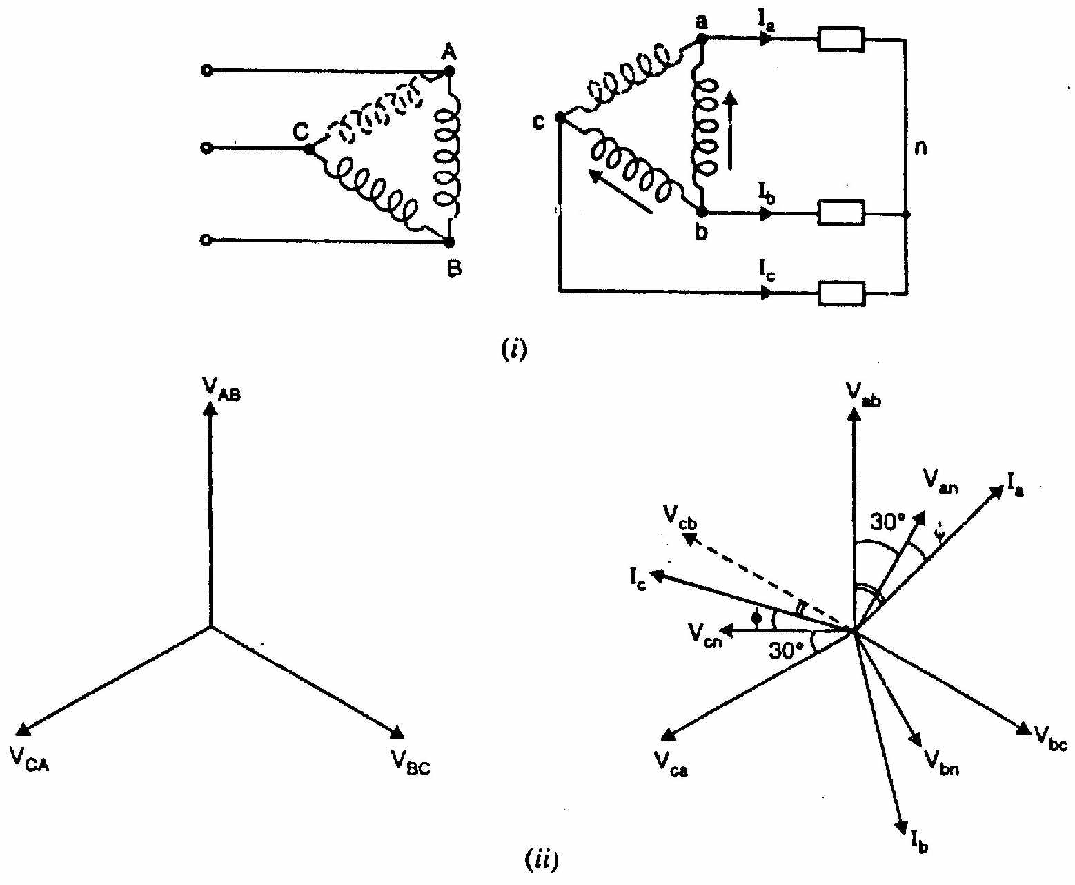
Appears in: 2018 Q4c, 2019 Q3b, 2020 Q4b, 2021 Q3b, 2023 Q4a
The scenario
You have a 3-phase Δ-Δ transformer bank with three single-phase units. One fails overnight. You cannot shut down the system. Can you continue serving the 3-phase load? Yes: using open-delta.
Why three-phase voltage remains balanced
Remove transformer TCA from the bank. Transformers TAB and TBC remain.
On the primary (supply) side: The 3-phase supply maintains VAB and VBC (two of the three line voltages). By KVL around the delta loop: VCA+VAB+VBC=0⟹VCA=−(VAB+VBC)
This voltage VCA is the third line voltage, and it is automatically determined by the other two. The 3-phase supply is balanced, so VCA is perfectly balanced with VAB and VBC.
On the secondary (load) side: Each remaining transformer has a secondary EMF proportional to its primary voltage × turns ratio K. So: Vab=K⋅VAB, Vbc=K⋅VBC.
By KVL on the secondary side: Vca=−(Vab+Vbc)=K⋅VCA
All three secondary line voltages are present and balanced. The load sees a balanced 3-phase supply.
Why capacity drops to 57.7%
Closed-Δ (3 transformers): Each transformer rated S=VI kVA. Total = 3S.
Open-Δ (2 transformers): Each transformer still handles its rated current I and rated voltage V. Each transformer's instantaneous power output alternates. For a balanced load with unity power factor, the effective power from each transformer:
Think about it geometrically. In a balanced 3-phase system, the voltages are 120° apart. When two transformers supply a balanced load, the phase angles of their voltage-current products are not both at unity power factor: they are at +30° and −30° from unity:
- Transformer 1 operates at power factor cos30°=3/2=0.866
- Transformer 2 operates at power factor cos30°=0.866 (by symmetry)
Each delivers power: V×I×0.866=0.866S
Total open-Δ power =2×0.866S=3S
SclosedSopen=3S3S=31=0.577=57.7%
Utilization factor
Each transformer is rated S kVA but works at 0.866S kW useful power. The transformer's KVA product (VI) is at its rated value, but only 86.6% of it goes to real power (the rest is reactive). So the transformer is 86.6% utilized: not 100%.
When to use it
- Emergency operation when one transformer fails.
- During maintenance (remove one transformer, keep supply going).
- For initial low-cost installation where future load growth is expected (start with two, add third later).
Sources: Books/Ch-32_04_Three_Phase_Transformers.md · ClassNoteByRaidah/Class_16.md
Induction Motor Topics (2018–2024)
IM-01: Air-Gap Power Ratios: Pg:Pr,Cu:Pm=1:s:(1−s)
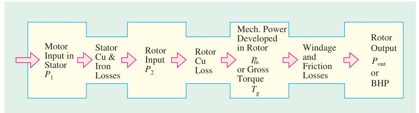
Appears in: 2018 Q5b, 2020 Q6b, 2021 Q6c, 2023 Q6a, 2024 Q5b
The power flow story
Electrical power enters the stator from the supply. Some is lost in stator resistance (stator Cu loss) and stator iron (core loss). The rest crosses the air gap as electromagnetic power: this is Pg, the air-gap power.
On the rotor side, Pg must go somewhere. Part becomes heat in the rotor resistance (rotor Cu loss). The rest becomes mechanical work delivered to the shaft. The question is: what fraction goes where?
Derivation from the equivalent circuit
At slip s, the rotor circuit has:
- Rotor resistance: R2
- Rotor reactance: sX2
- Rotor current: I2=sE2/R22+s2X22
Air-gap power per phase:
In the equivalent circuit, the air-gap power appears as the power in the resistance R2/s: Pg,phase=I22⋅sR2
Rotor copper loss per phase:
PCu,phase=I22⋅R2
Mechanical power per phase:
Pm,phase=Pg,phase−PCu,phase=I22⋅sR2−I22R2=I22R2(s1−1)=I22R2⋅s1−s
Ratios:
PgPCu=I22R2/sI22R2=s
PgPm=I22R2/sI22R2(1−s)/s=(1−s)
Therefore: Pg:PCu:Pm=1:s:(1−s)
Physical intuition
At full load slip s=0.04 (4%):
- 4% of air-gap power is wasted in rotor copper heat
- 96% becomes mechanical output
This is why induction motors are designed to run at small slip (2–5%). Small slip = small rotor copper loss = high rotor efficiency.
If you double the slip (say by adding rotor resistance), rotor copper loss doubles, and mechanical output drops. You're throwing away more power as heat in the rotor.
For the whole rotor: ηrotor=(1−s). At s=0.04: rotor efficiency = 96%. Very high: the rotor converts almost all received power to mechanical work.
Sources: Books/Ch-34_03_Power_Stages_and_Torque.md · ClassNoteByRaidah/Class_07.md · SlidesByMaam/L-05_ECE-2107.md
IM-02: Maximum Torque is Independent of Rotor Resistance
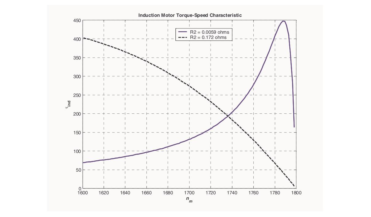
Appears in: CT-02 Q1, 2017 Q2b related, 2023 Q5, 2024 Q6a
Why this is surprising
Common intuition says: "More resistance = more voltage drop = less current = less torque." This is wrong in this context. Let's see why.
The full derivation and cancellation
Torque equation: T=R22+s2X22ksE22R2
Think of this as a function of two variables: s and R2. We want to find Tmax by varying both.
Finding the peak: Differentiate with respect to s (for fixed R2):
dsdT=kE22R2⋅(R22+s2X22)2(R22+s2X22)−s(2sX22)=0
Numerator = 0: R22+s2X22−2s2X22=0⟹R22=s2X22⟹smT=X2R2
Substituting smT=R2/X2 into the torque equation:
At the peak, s=R2/X2. Denominator: R22+s2X22=R22+X22R22⋅X22=R22+R22=2R22
Numerator: smTE22R2=X2R2⋅E22⋅R2=X2R22E22
Therefore: Tmax=k⋅2R22R22E22/X2=2X2kE22
The R22 terms in numerator and denominator cancel perfectly. Tmax has no R2 in it.
The intuition behind the cancellation
When you increase R2:
- The slip at peak torque increases (smT=R2/X2 grows).
- At the new peak slip, the rotor current is lower (higher impedance).
- But you're now evaluating at a higher slip, where more of the input power goes into the R2/s term: meaning the fraction going to resistance is higher.
These two effects exactly cancel: less current but higher per-unit power per unit current.
The result: The height of the torque peak is set entirely by the supply voltage and the standstill leakage reactance: two things that don't change when you add rotor resistance.
Practical application
Wound-rotor (slip-ring) induction motors can have external resistance added through the slip rings:
- For starting heavy loads: Add enough external resistance so R2+Rext=X2. This gives smT=1, meaning maximum torque at standstill. The motor starts with maximum possible torque.
- For speed control: Different values of external resistance shift the operating slip and thus the speed, for a given load torque.
- The max torque available is always the same regardless of how much resistance is inserted.
Sources: Books/Ch-34_02_Torque_and_Characteristics.md · ClassNoteByRaidah/Class_08.md · SlidesByMaam/L-06_ECE-2107.md
IM-03: Double-Field Revolving Theory: Why 1-Phase IM is Not Self-Starting
Appears in: 2018 Q8a, 2019 Q8b, 2020 Q8c, 2021 Q7a, 2023 Q8a, 2024 Q8a
The problem with single-phase
A 3-phase motor works because three windings, spatially displaced and phase-displaced in time, create a smoothly rotating field. Remove two phases and you have a single-phase winding that creates a pulsating (not rotating) field.
A pulsating field is different from a rotating field. It alternates back and forth along one axis. The question is: can this pulsating field still drive a rotor?
Ferraris' key insight (1885)
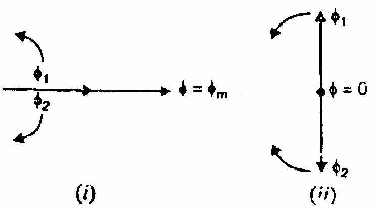
Italian physicist Galileo Ferraris showed that any pulsating magnetic field can be decomposed into two equal counter-rotating fields.
Mathematically: Φ=Φmsinωt
Can be written as: Φ=2Φmcos(ωt−α)+2Φmcos(ωt+α)
where α is the spatial angle. The first term rotates forward (counter-clockwise, say), the second rotates backward (clockwise). Each has magnitude Φm/2.
At any instant, the two counter-rotating phasors add up to give the original pulsating field along the axis.
Effect on the rotor: at standstill
Consider the forward-rotating field Φf=Φm/2 rotating at +Ns.
For the squirrel-cage rotor at rest (N=0): The forward field sees slip sf=(Ns−0)/Ns=1.
This field induces rotor currents and produces a forward torque Tf. This is exactly like a 3-phase motor at standstill: with the rotor field at slip 1.
Now consider the backward-rotating field Φb=Φm/2 rotating at −Ns.
For a stationary rotor, the backward field also sees a slip of 1 (it moves at −Ns relative to the ground, and the rotor is at rest, so relative speed =Ns).
The backward field produces a backward torque Tb, equal in magnitude to Tf (same slip, same rotor impedance).
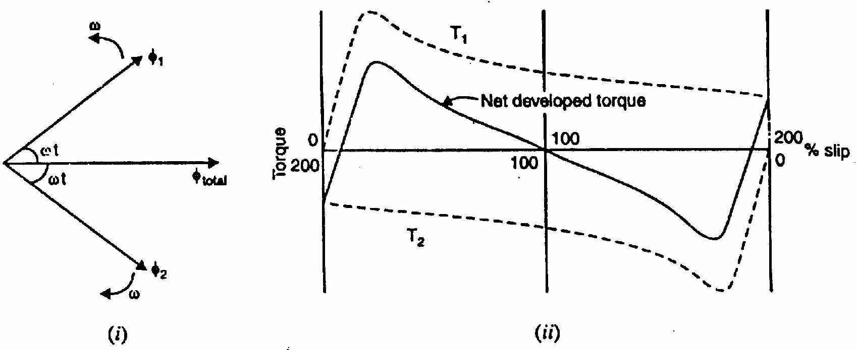
Net torque at standstill: T=Tf−Tb=0.
No starting torque. The motor just sits there.
Once you give it a push
Suppose you push the rotor to speed N in the forward direction.
Forward field slip: sf=(Ns−N)/Ns=s (say s=0.05 for running speed)
Backward field slip: The backward field rotates at −Ns. The rotor is at +N. Relative speed =−Ns−N=−(Ns+N). So: sb=NsNs+N=1+(1−s)=2−s
For s=0.05: sb=1.95.
Now look at the torque-slip curve:
- Forward field: slip = 0.05 (well below peak, in the high-torque stable region). Tf is large.
- Backward field: slip = 1.95 (past the peak, in the low-torque unstable region). Tb is small.
Net torque =Tf−Tb>0: The motor keeps accelerating and reaches a stable running speed.
Conclusion:
- At standstill: Tf=Tb, net = 0. Motor cannot start itself.
- Once running: Tf>Tb, net forward torque. Motor maintains speed.
- The direction of running depends on which way you push. The motor "doesn't care" which direction: it will run in whatever direction it was started.
Quantitative torque expression
Combining forward and backward torques: T=Tf(s)−Tb(2−s)
where: Tf(s)=R22+s2X22k1s⋅R2
Tb(2−s)=R22+(2−s)2X22k1(2−s)⋅R2
At s=1: these two are equal. At s<1 (forward rotation): Tf>Tb in typical motors.
Sources: Books/Chapman_Single_Phase_Motors.md · ClassNoteByRaidah/Class_17.md · SlidesByMaam/L-10_ECE-2107.md
IM-04: Blocked Rotor Test: Full Procedure and Why It's Needed
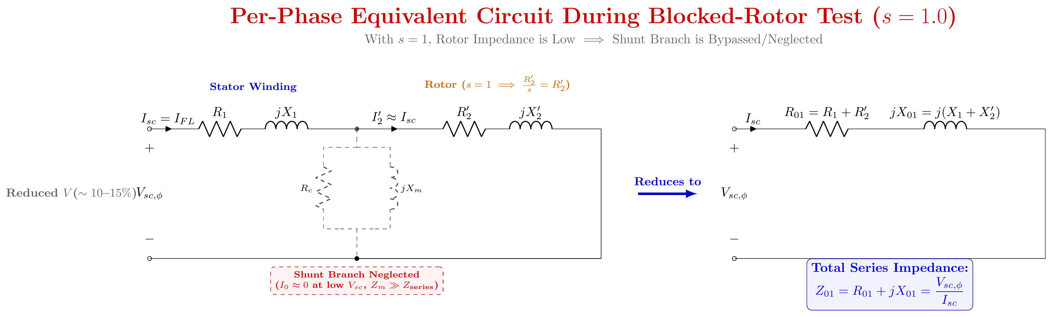
Appears in: CT-02 Q2, 2019 Q7a, 2020 Q7c, 2021 Q8, 2023 Q7a, 2024 Q7a
What this test does
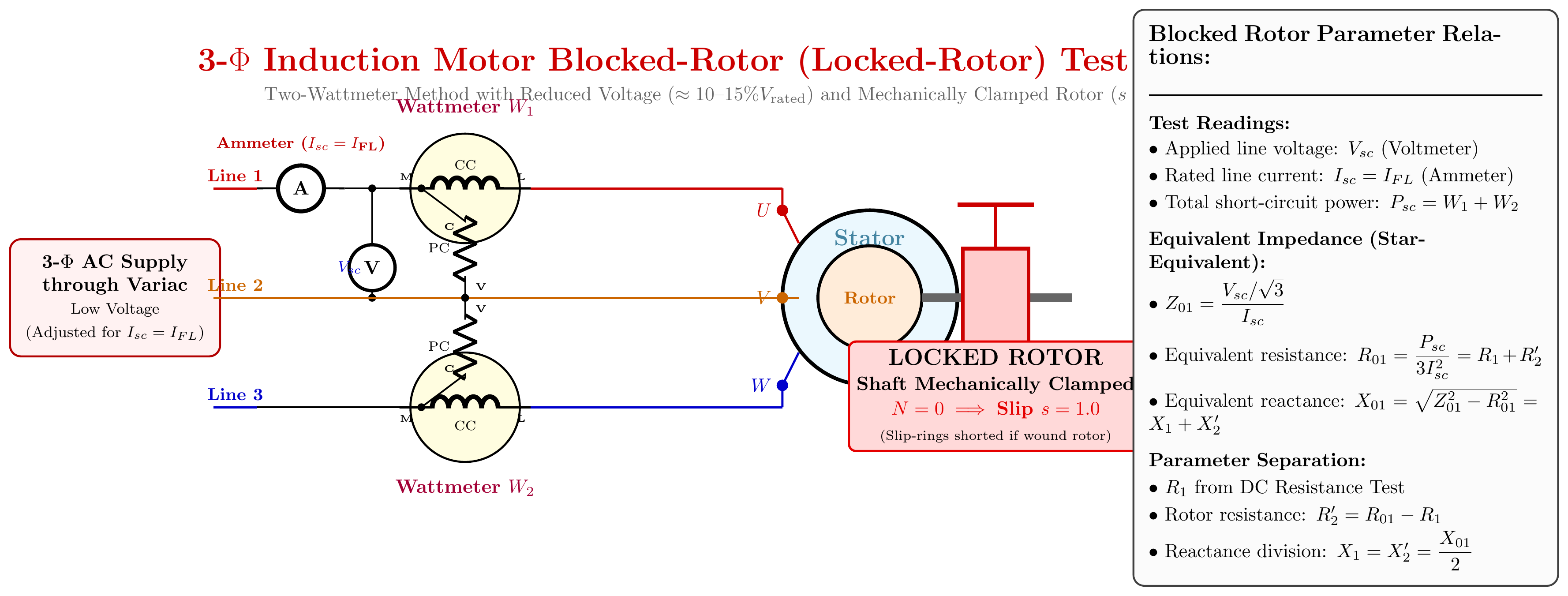
The blocked rotor test is to an induction motor what the short-circuit test is to a transformer. The rotor is physically locked, just as the secondary of a transformer is short-circuited. The result: the rotor is stationary, slip = 1, and the rotor presents its maximum impedance to the magnetic field.
This test lets us measure the series parameters of the motor equivalent circuit without needing to run the motor under full load.
The detailed procedure
Setup:
- Identify the rotor type. For squirrel-cage: just use the motor as-is. For wound-rotor (slip-ring): short the slip rings (remove external resistance).
- Lock the rotor shaft. Use a mechanical clamp, a brake, or a wooden block wedged between the stator housing and the shaft. The shaft must be absolutely stationary during the test.
- Connect measuring equipment: 3-phase variac, voltmeters, ammeters (one per phase is best for balance verification), two wattmeters (for 2-wattmeter method of 3-phase power measurement).
- Set the variac to minimum (zero output).
Running the test: 5. Slowly increase the variac until the ammeters read rated stator current. 6. Note: the voltage required is usually only 10–20% of rated voltage. This is because the rotor is stationary: no back-EMF opposing current. The full motor impedance is much lower than normal running. 7. Read and record: line voltage Vsc, line current Isc (should equal rated), total 3-phase power Psc=W1+W2. 8. Do not keep the test running for more than 30–60 seconds. Rated current is flowing through windings with a stationary rotor: all power is being converted to heat. The windings will overheat quickly. 9. Reduce variac to zero and disconnect supply.
Why low voltage means negligible core loss
Core (iron) loss is approximately proportional to V2 (since B∝V, and Peddy∝B2, Physt∝B1.6).
At 15% of rated voltage: core loss ≈(0.15)2×PFe,rated=0.0225×PFe,rated
Only 2.25% of rated core loss: completely negligible.
So Psc = stator copper loss + rotor copper loss. This is what we call full-load copper loss.
Parameter extraction (star connection)
Convert line values to per-phase values (divide voltages by 3 for star):
Z01=IscVsc/3
R01=3Isc2Psc
X01=Z012−R012
Separate stator and rotor components:
- Measure stator resistance R1 separately (DC resistance × 1.3 for AC skin-effect correction).
- R2′=R01−R1
- Assume equal leakage: X1=X2′=X01/2
The five things this test gives you
- Full-load copper losses → Calculate efficiency at any load.
- Series impedance R01, X01 → Complete the equivalent circuit.
- Starting current at rated voltage: Istart=Isc×VscVrated This lets you check if DOL starting is safe or if a starter is needed.
- Starting torque: Tstart∝NsIstart2⋅R2′
- Circle diagram construction: The short-circuit current magnitude (Isc,full voltage) and power factor (cosϕsc) define the circle diagram's short-circuit point.
Sources: Books/Ch-35/01_Circle_Diagram_and_Testing.md · ClassNoteByRaidah/Class_09.md · SlidesByMaam/L-09_ECE-2107.md
Source questions: PrevYearQuestions (all years)
← 2024 Answer | 🏠 Index | (end)