answers_explanation/2017_answer.md
23.7 KB · commit d2f3b6e
(start) | 🏠 Index | 2018 Answer →
ECE 2207: 2017 Semester Final: Explanation Style Answers
RUET · ECE Dept · 2nd Year Odd Semester 2017
Deep tutorial-style explanations focusing on first-principles physics, "why over what", step-by-step logic, and practical engineering intuition. Core cross-cutting theory topics are detailed in 2018_2024_answer.md.
SECTION - A (Induction Motors: Q1 to Q4)
Question 1
Q1(a): Why is an Induction Motor Called a "Rotating Transformer"?
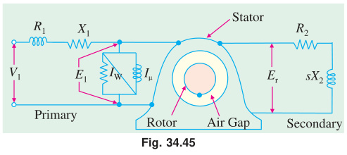
The Physical Analogy:
A conventional static transformer transfers energy between two electrically isolated circuits via mutual electromagnetic induction through a stationary magnetic core. The 3-phase induction motor operates on the exact same fundamental mechanism across an air gap:
- Primary Circuit (Stator): Connects to the AC power grid, drawing alternating current that establishes mutual magnetic flux across the air gap.
- Secondary Circuit (Rotor): Consists of closed, short-circuited conducting bars. The mutual magnetic field induces secondary voltages and circulating secondary currents by Faraday's Law.
- Standstill Identity (s=1.0): When the rotor is locked, the rotor frequency equals the supply frequency (fr=f). The machine is mathematically and physically identical to a short-circuited 3-phase transformer.
- The Distinction ("Rotating"): In a transformer, the secondary winding is fixed to the iron core. In an induction motor, the secondary conductors are housed on a freely rotating cylindrical rotor. Part of the induced electrical energy is converted into mechanical kinetic energy, and the frequency of induced rotor EMF is throttled down by slip: fr=sf.
Q1(b): Proof That 3-Phase Stator Windings Produce a Uniformly Rotating Flux
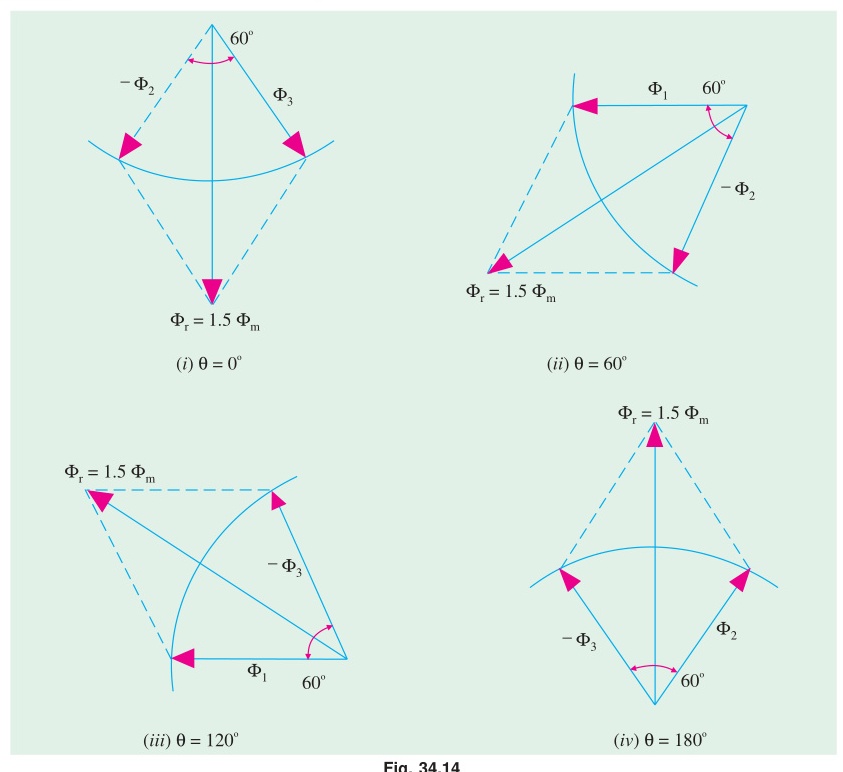
Setup:
Three identical stator coils displaced 120° apart in space around the cylindrical stator periphery carry balanced 3-phase currents displaced 120° apart in time: ΦR=Φmsinωt,ΦY=Φmsin(ωt−120°),ΦB=Φmsin(ωt+120°)
Resolving into Orthogonal Spatial Components:
Taking the R-phase spatial axis as horizontal (+X axis):
-
Horizontal (X) Component: Φx=ΦR+ΦYcos120°+ΦBcos240° Φx=Φmsinωt−21Φm[sin(ωt−120°)+sin(ωt+120°)] Using sin(A−B)+sin(A+B)=2sinAcosB: sin(ωt−120°)+sin(ωt+120°)=2sinωtcos120°=−sinωt Φx=Φmsinωt−21Φm(−sinωt)=23Φmsinωt
-
Vertical (Y) Component: Φy=ΦYsin120°+ΦBsin240°=23Φm[sin(ωt−120°)−sin(ωt+120°)] Using sin(A−B)−sin(A+B)=−2cosAsinB: Φy=23Φm[−2cosωt(23)]=−23Φmcosωt
-
Resultant Flux Magnitude and Spatial Rotation: Φr=Φx2+Φy2=(23Φm)2(sin2ωt+cos2ωt)=1.5Φm=constant θ=tan−1(ΦxΦy)=tan−1(sinωt−cosωt)=ωt−90° The resultant flux has constant magnitude 1.5Φm and sweeps smoothly around the stator bore at synchronous speed ω=2πf electrical rad/s (Ns=P120f rpm).
Q1(c): 6-Pole, 50 Hz Induction Motor Driven Mechanically at 1000 rpm
Given Data:
- Poles P=6, Frequency f=50 Hz
- Driven rotor speed N=1000 rpm
Step-by-Step Analysis:
- Synchronous Speed of Stator RMF: Ns=P120f=6120×50=1000 rpm
- Operating Slip: s=NsNs−N=10001000−1000=0
- Induced Rotor EMF Frequency and Magnitude: fr=sf=0×50=0 Hz E2s=sE2=0 V
- Physical Explanation: When the rotor is driven at the exact same speed and direction as the rotating magnetic field, there is zero relative velocity between the stator magnetic flux lines and the rotor conductors. The conductors never cut any flux lines (dΦ/dt=0). By Faraday's Law, no EMF is induced in the rotor bars, no rotor current flows, and electromagnetic torque is zero. The motor neither absorbs nor produces electrical power.
Question 2
Q2(a): Torque-Slip Characteristic and the Impact of Rotor Resistance
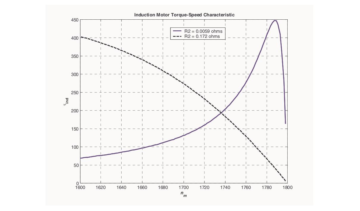
The torque equation of an induction motor is: T=R22+s2X22ksE22R2
- Low-Slip Zone (s<smT): Rotor reactance is negligible (sX2≪R2). Torque is roughly proportional to slip: T∝R2s. Higher rotor resistance reduces torque in this linear operating region.
- High-Slip Zone (s>smT): Rotor reactance dominates (sX2≫R2). Torque is inversely proportional to slip: T∝sX22R2. Higher rotor resistance increases torque in this region.
- Effect of Increasing R2 on the Curve:
- The breakdown torque magnitude Tmax=2X2kE22 remains completely unchanged.
- The slip at which peak torque occurs shifts upward: smT=X2R2.
- Starting torque (s=1.0) increases significantly until R2=X2, where starting torque reaches the absolute breakdown torque limit (Tst=Tmax).
Q2(b): Proof: TmaxTf=a2+sf22asf
Torque at full-load slip sf: Tf=R22+sf2X22ksfE22R2 Maximum breakdown torque occurs at smT=X2R2=a: Tmax=2X2kE22 Dividing Tf by Tmax: TmaxTf=2X2kE22R22+sf2X22ksfE22R2=R22+sf2X222sfR2X2 Divide both numerator and denominator by X22: TmaxTf=(X2R2)2+sf22sf(X2R2)=a2+sf22asf where a=X2R2=smT. (Proved)
Q2(c): Numerical: 4-Pole, 50 Hz IM Torque Ratio and Speed
Given Data:
- Poles P=4,f=50 Hz⟹Ns=1500 rpm
- Rotor parameters: R2=0.04Ω,X2=0.20Ω
- Full-load speed N=1440 rpm
Step-by-Step Solution:
- Full-Load Operating Slip: sf=15001500−1440=150060=0.04
- Slip and Speed at Maximum Torque: a=smT=X2R2=0.200.04=0.20(20% slip) NmT=Ns(1−smT)=1500×(1−0.20)=1200 rpm
- Ratio of Maximum Torque to Full-Load Torque (Tmax/TFL): TmaxTFL=a2+sf22asf=(0.20)2+(0.04)22×0.20×0.04=0.040+0.00160.016=0.04160.016≈0.3846 TFLTmax=0.38461=2.60
Question 3
Q3(a): Step-by-Step Development of Induction Motor Equivalent Circuit
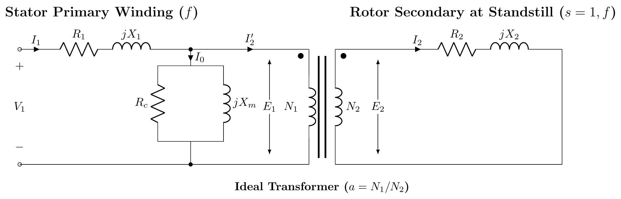
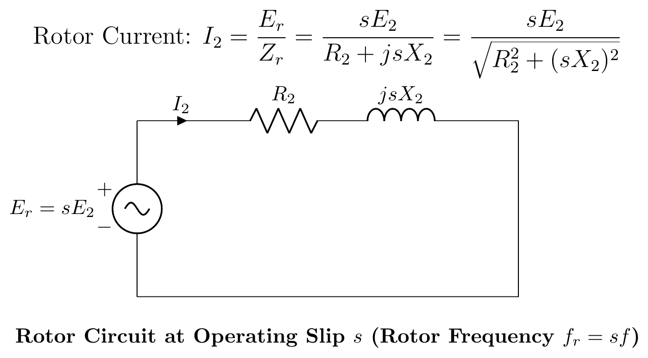
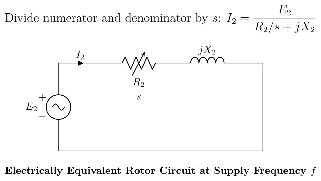
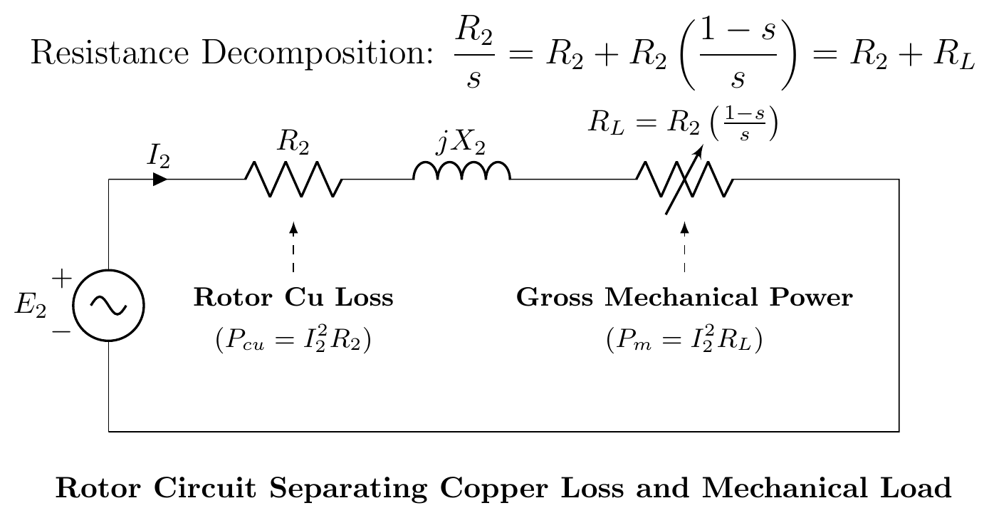
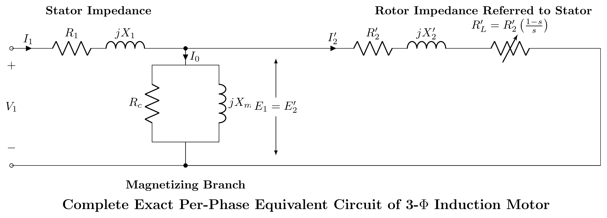
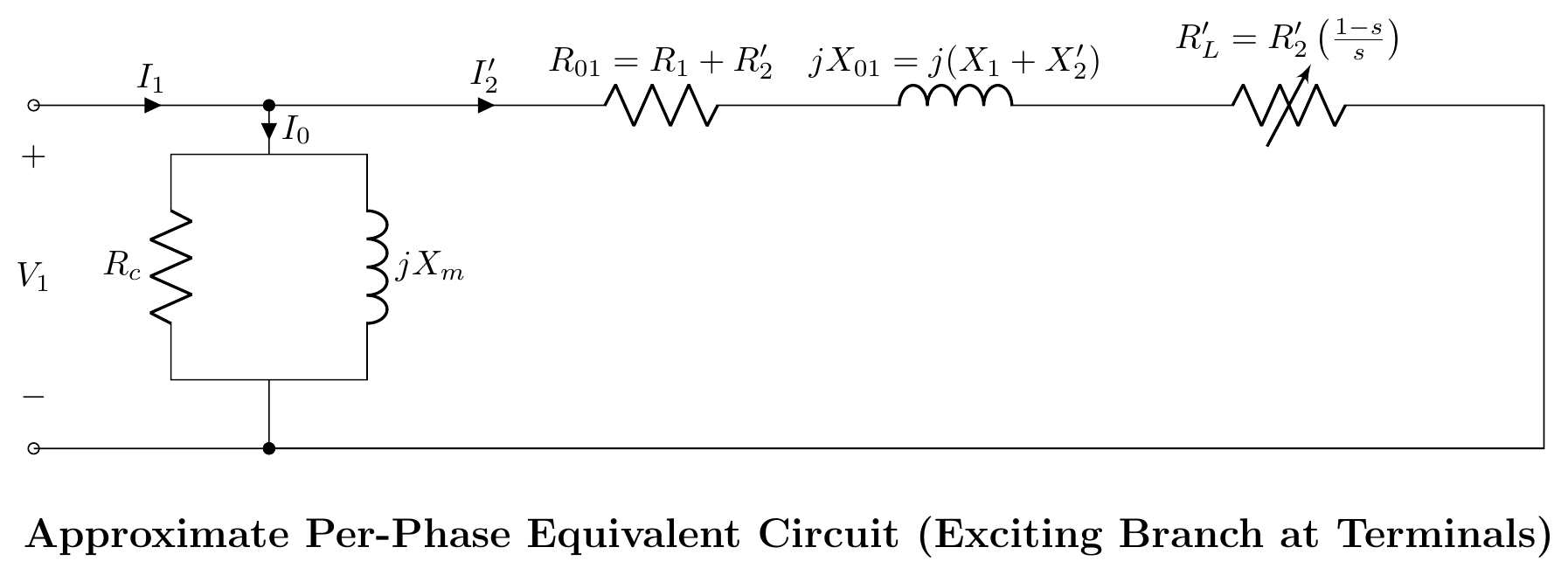
- Step 1: Transformer model at standstill (s=1). Both stator and rotor operate at line frequency f.
- Step 2: Rotor at slip s. Induced EMF is sE2, frequency is sf, and reactance is sX2.
- Step 3: Divide rotor impedance by s to refer frequency to line frequency f. The rotor resistance becomes fictitious variable resistance R2/s.
- Step 4: Split R2/s into internal copper loss resistance R2 and mechanical load resistance RL=R2(s1−s).
- Step 5: Eliminate the ideal transformer by referring rotor parameters to the stator side (R2′=a2R2,X2′=a2X2).
- Step 6: Approximate circuit formed by shifting the shunt magnetizing branch to the input terminals.
Q3(b): Power Flow Equation: Pg:Pr,Cu:Pm=1:s:(1−s)
See full derivation in IM-01: Air-Gap Power Ratios.
- Total air-gap power transferred into rotor: Pg=3I22sR2.
- Rotor copper loss dissipated as heat: Pr,Cu=3I22R2=sPg.
- Net developed mechanical power: Pm=Pg−Pr,Cu=(1−s)Pg.
- Ratio: Pg:Pr,Cu:Pm=1:s:(1−s).
Q3(c): Circle Diagram Construction and Practical Significance
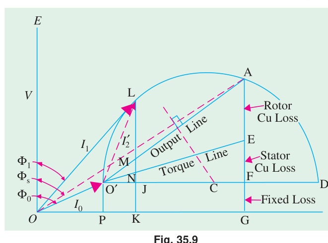
The circle diagram is a graphical circle locus representing the locus of the stator current phasor as slip varies from 0→1→∞.
- Test Data Required:
- No-load test: Determines no-load current I0 and phase angle ϕ0 (locates point O′).
- Blocked-rotor test: Scaled to full rated voltage to find short-circuit current Isc and phase angle ϕsc (locates point S).
- Stator resistance R1: Divides the vertical drop at S into stator copper loss and rotor copper loss.
- Why It Is Useful: From this single circular drawing, engineers can read off stator current, power factor, slip, efficiency, rotor copper loss, mechanical power, and breakdown torque for any operating point without performing complex AC algebra.
Question 4
Q4(a): Why Single-Phase Induction Motors Inherently Produce No Starting Torque
See detailed breakdown in IM-03: Single-Phase Induction Motor: Double Revolving Field Theory.
- A single stator winding produces a pulsating flux Φ(t)=Φmsinωt along a single axis.
- By Ferraris' theorem, this decomposes into two equal and opposite counter-rotating fields (Φf=Φm/2 at +Ns and Φb=Φm/2 at −Ns).
- At standstill (N=0), both forward and backward slips are 1.0 (sf=sb=1.0).
- Forward torque Tf and backward torque Tb are identical in magnitude and opposite in direction.
- Resultant net torque is strictly zero (Tnet=Tf−Tb=0).
Q4(b): Why Permanent-Split Capacitor Motors Run More Quietly Than Capacitor-Start Motors
- Capacitor-Start Motor:
- Uses an electrolytic capacitor in the auxiliary branch during starting.
- At ~75% speed, a centrifugal switch disconnects the auxiliary winding.
- During running, the motor operates solely on its single main winding. The magnetic field collapses into a pulsating single-phase field, producing double-frequency torque pulsations (100 Hz hum in a 50 Hz system) and mechanical vibration.
- Permanent-Split Capacitor (PSC) Motor:
- The auxiliary winding and a continuous-duty oil-filled AC capacitor remain connected permanently during both starting and running.
- The motor operates continuously as a true two-phase machine.
- With two windings 90° apart in space carrying currents 90° apart in time, the stator produces a continuous, smooth, circular rotating magnetic field at all times.
- Torque pulsations are practically eliminated, there is no mechanical centrifugal switch to click or fail, and the motor runs with whisper-quiet smoothness.
Q4(c): How an Auxiliary Winding Provides Starting Torque
To convert a stationary pulsating field into a rotating magnetic field, an auxiliary winding is introduced:
- Spatial Displacement: Wound on the stator displaced by 90° electrical space from the main winding.
- Temporal Phase Displacement: Current in the auxiliary winding is forced out of phase with main current by:
- Higher resistance (R/L split-phase).
- Series capacitor (capacitor-start).
- If main current is im(t)=Imsinωt and auxiliary current is ia(t)=Iasin(ωt+90°), the resultant flux vector rotates around the air gap, dragging the rotor along and developing starting torque.
SECTION - B (Transformers: Q5 to Q8)
Question 5
Q5(a): Transformer Definition and Engineering Advantages
A static electromagnetic apparatus that transforms AC electrical energy between circuits at identical frequency through mutual inductive coupling.
- Advantages:
- Transmission Efficiency: Stepping voltage up to hundreds of kilovolts slashes line current, drastically reducing I2R transmission line losses (Ploss∝1/V2).
- Near-Zero Maintenance: Having zero moving parts eliminates mechanical friction, bearing wear, and spark generation.
- Unmatched Efficiency: Large transformers achieve 98% to 99.5% efficiency.
- Galvanic Isolation: Isolates high-voltage utility transmission lines from low-voltage consumer distribution circuits.
Q5(b): Operating Principle of an Ideal Transformer
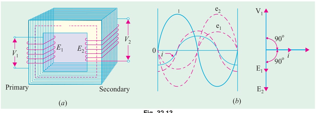
An ideal transformer assumes zero winding resistances, zero leakage flux, zero core losses, and infinite core permeability:
- Applied AC voltage v1(t) establishes alternating core flux Φ(t)=Φmsinωt.
- By Faraday's Law: e1(t)=−N1dtdΦ,e2(t)=−N2dtdΦ
- Voltage transformation: V2V1=E2E1=N2N1=a
- Since the ideal machine is completely lossless, instantaneous input power equals output power (v1i1=v2i2): I2I1=V1V2=N1N2=a1
Q5(c): Efficiency Calculations: 25 kVA Transformer
Given Data:
- Rating S=25 kVA=25,000 VA
- Iron loss PFe=350 W (constant)
- Full-load copper loss PCu,FL=400 W
1. Full-Load Performance (x=1.0):
- Unity Power Factor (cosϕ=1.0): Pout=25,000×1.0=25,000 W Ploss=350+400=750 W⟹η=25,75025,000×100%=97.09%
- 0.8 Lagging Power Factor (cosϕ=0.8): Pout=25,000×0.8=20,000 W Ploss=750 W⟹η=20,75020,000×100%=96.39%
2. Half-Load Performance (x=0.5):
- Half-load copper loss: PCu=(0.5)2×400=0.25×400=100 W.
- Total losses: Ploss=350+100=450 W.
- Unity Power Factor: Pout=12,500 W⟹η=12,95012,500×100%=96.53%
- 0.8 Lagging Power Factor: Pout=10,000 W⟹η=10,45010,000×100%=95.69%
Question 6
Q6(a): Complete Full-Load Phasor Diagram
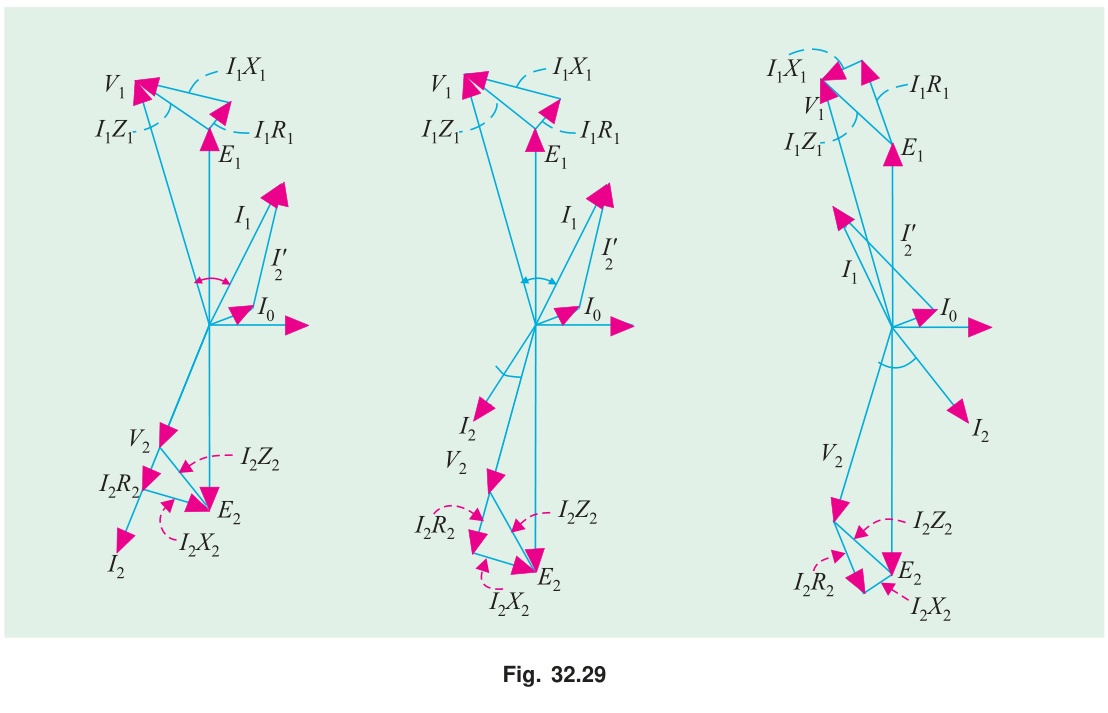
Shows core flux Φ reference, induced EMFs E1,E2 lagging by 90°, secondary load drop triangle V2+I2R2+jI2X2=E2, and primary voltage equation V1=−E1+I1R1+jI1X1.
Q6(b): Hysteresis Loss and Eddy Current Loss
- Hysteresis Loss (Ph): Energy dissipated as heat due to the friction of microscopic magnetic domains aligning and realigning each AC half-cycle. Governed by the Steinmetz equation: Ph=KhfBm1.6Vcore Minimized by selecting silicon alloy steel with a narrow B−H hysteresis loop.
- Eddy Current Loss (Pe): Ohmic I2R loss caused by circulating currents induced within the conductive steel laminations by the alternating flux: Pe=Kef2Bm2t2Vcore Minimized by slicing the core into thin (t≈0.35 mm), varnish-insulated laminations.
Q6(c): 500 kVA, 2300/208V Parameter Extraction Referred to Secondary
Given Data:
- Rating: 500 kVA,2300/208 V,50 Hz
- Turns ratio: a=2082300=11.0577⟹a2=122.27
- OC Test (LV side, 208 V): V0=208 V,I0=85 A,W0=1800 W
- SC Test (HV side, 2300 V): Vsc=95 V,Isc=217.4 A,Wsc=8200 W
1. Series Parameters on HV Side:
Z01=IscVsc=217.495=0.4370Ω R01=Isc2Wsc=(217.4)28200=47,262.768200=0.1735Ω X01=Z012−R012=(0.4370)2−(0.1735)2=0.1910−0.0301=0.4011Ω
2. Series Parameters Referred to Secondary (LV Side):
Divide all series impedances by a2=122.27: R02=a2R01=122.270.1735=1.419×10⁻³Ω=1.419 mΩ X02=a2X01=122.270.4011=3.280×10⁻³Ω=3.280 mΩ Z02=a2Z01=122.270.4370=3.574×10⁻³Ω=3.574 mΩ
Question 7
Q7(a): Why Open-Delta is Limited to 57.7% of Normal Δ-Δ Capacity
See detailed proof and vector diagrams in T-04: Open-Delta Connection: Why 57.7% and When to Use It.
- Closed delta bank rating: SΔ=3VI.
- Open delta rating: SV=3VI.
- Capacity ratio: SΔSV=31=57.7%.
- Transformer utilization factor: 2VI3VI=23=86.6%.
Q7(b): Parallel Operation Conditions of 3-Phase Transformers
- Equal Voltage Ratio (prevents no-load circulating currents).
- Identical Polarity (prevents dead short-circuits).
- Equal Per-Unit Impedances (ensures proportional load sharing).
- Equal X/R Ratio (ensures equal operating power factor).
- Identical Phase Sequence and Zero Relative Phase Shift / Same Vector Group (prevents catastrophic line-to-line circulating currents).
Q7(c): 60 Hz Transformer Operated on 50 Hz Supply
Physical Impact:
From E≈V=4.44fNΦm: Φm∝fV If a transformer designed for 60 Hz is connected to a 50 Hz system at rated voltage: Φm,60Φm,50=5060=1.20
- Core flux increases by 20%, pushing the silicon steel deep into magnetic saturation.
- Magnetizing current spikes dramatically, causing core overheating and humming noise.
- Hysteresis loss increases (∝fBm1.6), but eddy current loss stays roughly constant (∝f2Bm2∝f2(V/f)2=const).
- Feasibility of Supplying 15 kVA at 415 V:
- The load of 15 kVA is below the 18 kVA rated capacity (83.3% load), leaving substantial thermal margin in the copper conductors.
- Operating at reduced secondary voltage (415 V vs rated 480 V) reduces excitation stress.
- Conclusion: The transformer can safely supply the 15 kVA load, provided core temperature is monitored to avoid thermal runaway from saturation heating.
Question 8
Q8(a): Instrument Transformers and the Potential Transformer (PT)
- Instrument Transformers: Specialized precision transformers that step down lethal voltages and massive currents to standardized, safe metering levels (110 V for PTs, 5 A for CTs), isolating personnel and instruments from high-voltage switchgear.
- Potential Transformer (PT): An extremely accurate step-down transformer connected in parallel across high-voltage power lines. Its secondary is terminated with high-impedance voltmeters or protection relays. The secondary must never be short-circuited, as a short circuit draws destructive current across the small winding impedance.
Q8(b): Magnetizing Inrush Current and Mitigation
- Why Inrush Current Occurs: When an unloaded transformer is switched onto an AC line, the core flux Φ(t)=∫v(t)dt requires a transient DC offset to satisfy initial boundary conditions. If the breaker closes at voltage zero crossing, and the core carries residual flux (Φr), the required flux can peak at: Φpeak≈2Φm+Φr≈2.5 to 2.8Φm This drives the iron core deep into saturation, reducing core permeability to that of air (μr→1). With core inductance collapsed, a massive inrush current (8 to 15 times full-load rated current) surges into the primary, decaying over several cycles.
- Mitigation Techniques:
- Point-on-Wave (POW) Controlled Switching: Closing circuit breaker poles at the crest of the AC voltage wave (where required flux starts at zero).
- Pre-Insertion Resistors: Dampening the inrush current transient via series resistors bypassed after 2–3 cycles.
Q8(c): 200/400V Step-Up Transformer Numerical Problem
Given Data:
- Primary rating V1=200 V, Secondary V2=400 V (step-up)
- Turns ratio: a=N2N1=400200=0.5
- Parameters referred to LV (primary) side: Req=0.15Ω,Xeq=0.37Ω,Rc=600Ω,Xm=300Ω
- Secondary load: I2=10 A at cosϕ2=0.8 lagging (sinϕ2=0.6).
Step-by-Step Solution:
- Reflect Secondary Current to Primary (LV) Side: I2′=aI2=0.510=20 A With secondary terminal voltage referred to primary taken as reference: V2′=V2′∠0°=200∠0° V I2′=20∠−cos−1(0.8)=20(0.8−j0.6)=16.0−j12.0 A
- Primary Terminal Voltage (V1): V1=V2′+I2′(Req+jXeq) I2′(Req+jXeq)=(16−j12)(0.15+j0.37)=(2.40+4.44)+j(5.92−1.80)=6.84+j4.12 V V1=(200+6.84)+j4.12=206.84+j4.12 V V1=(206.84)2+(4.12)2=206.88 V
- Core Excitation Current (I0): Ic=RcV1=600206.88=0.3448 A,Im=XmV1=300206.88=0.6896 A I0=0.3448−j0.6896 A
- Total Primary Input Current (I1): I1=I0+I2′=(0.3448−j0.6896)+(16.0−j12.0)=16.3448−j12.6896 A I1=(16.3448)2+(12.6896)2=267.15+161.03=428.18=20.69 A
- Secondary Terminal Voltage: V2=aV2′=0.5200=400.0 V
Source: PrevYearQuestions/2017.md
(start) | 🏠 Index | 2018 Answer →