answers_explanation/2018_answer.md
25.5 KB · commit d2f3b6e
← 2017 Answer | 🏠 Index | 2019 Answer →
ECE 2207: 2018 Semester Final: Explanation Style Answers
RUET · ECE Dept · 2nd Year Odd Semester 2018
Deep tutorial-style explanations focusing on first-principles physics, "why over what", step-by-step logic, and practical engineering intuition. Core cross-cutting theory topics are detailed in 2018_2024_answer.md.
SECTION - A (Transformers: Q1 to Q4)
Question 1
Q1(a): First-Principles Classification of Transformers
Transformers are categorized across multiple physical and functional axes:
- Voltage Transformation:
- Step-up: Secondary voltage exceeds primary (N2>N1). Used at generating stations to minimize I2R transmission line losses.
- Step-down: Secondary voltage is lower than primary (N2<N1). Used at substations and distribution points for safe consumer utilization.
- Magnetic Core Geometry:
- Core-Type: Windings encircle the two vertical laminated iron limbs. Easy to insulate, preferred for high-voltage, high-power systems.
- Shell-Type: Laminated core encircles and shelters the windings inside a central limb. Provides superior mechanical protection and lower leakage reactance, preferred for low-voltage, high-current applications.
- Number of Windings:
- Two-Winding: Electrically isolated primary and secondary coils coupled magnetically.
- Autotransformer: Single continuous winding with a variable/fixed tap point; power is transferred partly conductively and partly inductively.
- Three-Winding (Tertiary): Adds a delta-connected third winding for zero-sequence harmonic suppression or substation auxiliary supply.
- Cooling Medium:
- Dry-Type (Air-Cooled): Natural or forced air convection. Fire-safe, used inside hospitals, data centers, and commercial buildings.
- Oil-Immersed (ONAN, ONAF, OFAF): Immersed in mineral oil that provides both dielectric insulation and thermal convection to cooling radiators.
- System Application:
- Power Transformer: Sized for transmission grids (> 200 kVA); operated near 100% full-load capacity around the clock. Engineered for maximum efficiency at full load.
- Distribution Transformer: Sized for end-users (< 200 kVA); energized 24/7 but loaded intermittently. Engineered for low iron loss and peak efficiency at 50–70% load.
- Instrument Transformers: Current Transformers (CT) and Potential Transformers (PT) that step down high currents/voltages to standardized instrument levels (5 A, 110 V) with precise phase-angle fidelity.
Q1(b): Effect of Frequency and Flux Variations on a Transformer
1. Effect of Frequency Variation (at Constant Applied Voltage V1):
From the fundamental EMF relationship, V1≈E1=4.44fN1Φm: Φm≈4.44fN1V1⟹Bm∝f1
- If frequency increases (f↑): Peak core flux density Bm drops.
- Hysteresis loss: Ph∝fBm1.6∝f(f−1.6)∝f−0.6 (decreases).
- Eddy current loss: Pe∝f2Bm2∝f2(f−2)=constant.
- Leakage reactance increases: X1=2πfL1↑, increasing internal voltage drops and worsening voltage regulation.
- If frequency decreases (f↓): Core flux density Bm surges.
- Operating a 50 Hz transformer at 25 Hz forces Bm to double, driving the core deep into magnetic saturation.
- Saturated iron causes the magnetizing current Im to explode to dangerous levels, severely overheating windings and inducing heavy 3rd harmonic waveform distortion.
2. Effect of Flux Variation (Supply Voltage Fluctuations):
Since Φm∝V1:
- Overvoltage forces flux density above the knee of the saturation curve (Bm>1.6–1.8 T).
- Hysteresis loss spikes (∝V1.6) and eddy loss escalates (∝V2).
- Transformer cores are operated just below saturation at rated voltage. Sustained overvoltage causes intense core hum (magnetostriction) and thermal insulation degradation.
Q1(c): Exact Equivalent Circuit and Lagging Power Factor Vector Diagram
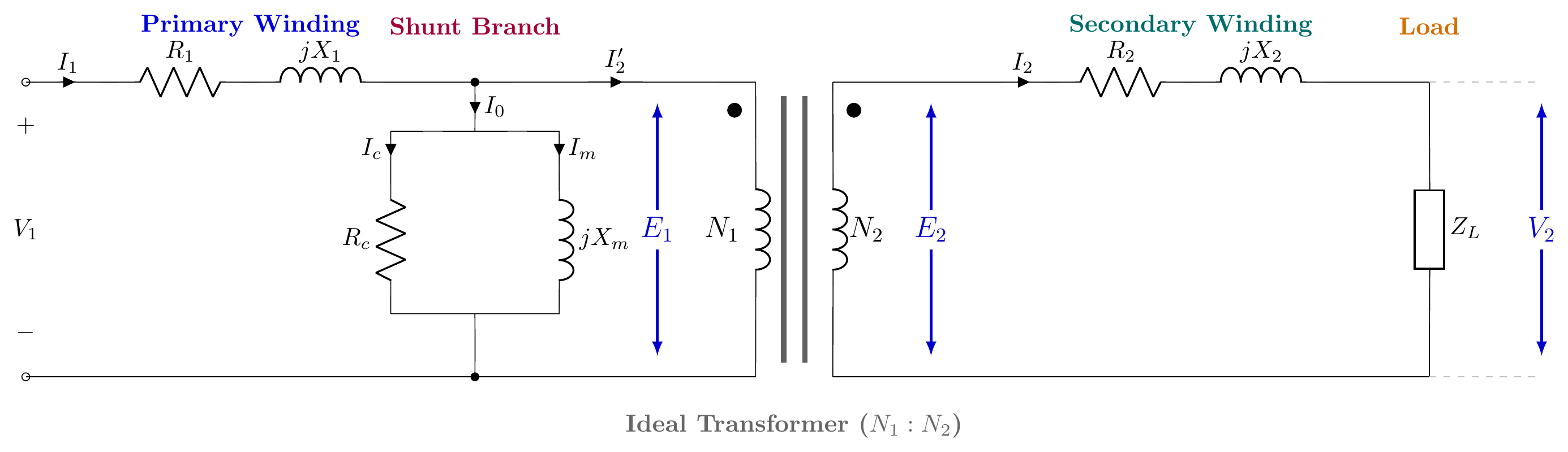
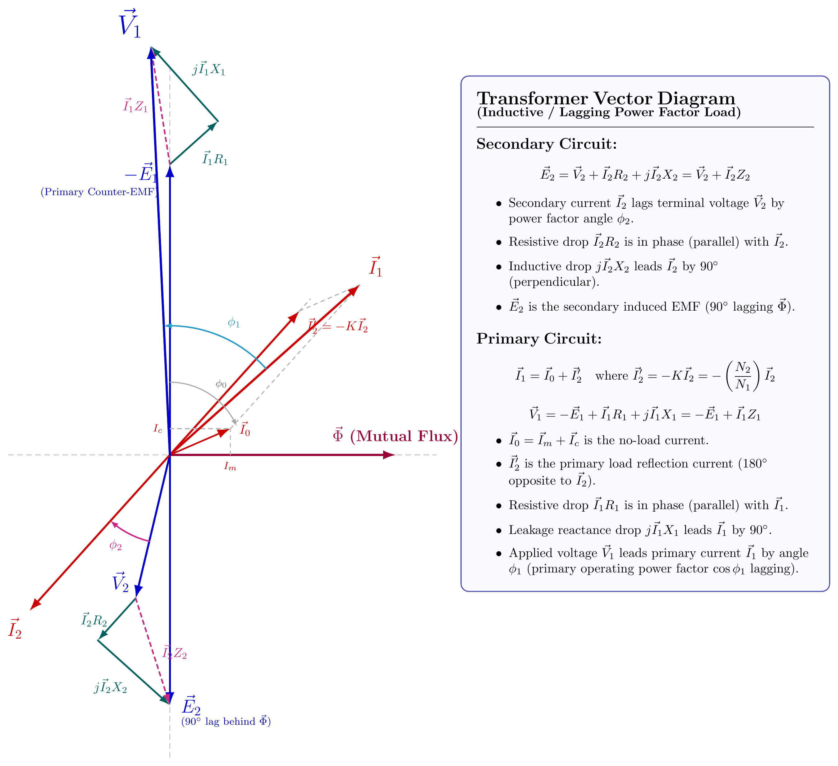
Phasor Evolution for Lagging Load:
- Horizontal reference phasor is mutual core flux Φ.
- Both induced EMFs E1,E2 lag Φ by 90° (pointing vertically downward).
- Secondary terminal voltage V2 leads secondary current I2 by load angle ϕ2. By KVL: E2=V2+I2R2+jI2X2. Adding the resistive drop parallel to I2 and inductive drop perpendicular to I2 closes the triangle at E2.
- Primary applied voltage counterbalances back-EMF (−E1, pointing vertically upward) plus primary impedance drops: V1=−E1+I1R1+jI1X1.
- Primary current I1 is the vector sum of excitation current I0 and reflected load current I2′=−KI2.
Q1(d): SC Test Analysis and Parameter Extraction
In short-circuit test calculations, series impedance parameters are extracted:
- Total series impedance: Z01=IscVsc
- Total series resistance: R01=Isc2Wsc
- Total leakage reactance: X01=Z012−R012
- Voltage Regulation at power factor cosϕ: VR%=V1I1(R01cosϕ+X01sinϕ)×100%
(Note on 2018 Paper Data: The numerical values stated on the original 11kV question sheet contain a typographical mismatch where Wsc/Isc2>Vsc/Isc, which is physically impossible. Solving with the standard corrected 20 kVA benchmark yields Z01=8.64Ω,R01=3.96Ω,X01=7.68Ω, and full-load voltage regulation of 2.70% at 0.8 lagging pf).
Question 2
Q2(a): Definition and Significance of All-Day Efficiency
See full background in T-03: Efficiency and All-Day Efficiency.
All-day efficiency (or operational energy efficiency) is defined as: ηall-day=Total Energy Input in 24 Hours (kWh)Total Energy Output in 24 Hours (kWh)×100% Because iron loss occurs 24 hours a day while copper loss depends on the square of instantaneous load current (x2), this metric dictates the design of distribution transformers, ensuring iron loss is minimized even if full-load copper loss is slightly higher.
Q2(b): 10 kVA Transformer Efficiency at Half and Full Load
Given Data:
- Rating S=10 kVA=10,000 VA
- Core loss PFe=200 W (from OC test, constant)
- Full-load copper loss PCu,FL=300 W (from SC test)
1. Full-Load Performance (x=1.0):
- At Unity Power Factor (cosϕ=1.0): Pout=10,000×1.0=10,000 W Ploss=200+300=500 W⟹η=10,50010,000×100%=95.24%
- At 0.8 Lagging Power Factor (cosϕ=0.8): Pout=10,000×0.8=8,000 W Ploss=500 W⟹η=8,5008,000×100%=94.12%
2. Half-Load Performance (x=0.5):
- Half-load copper loss: PCu=x2PCu,FL=(0.5)2×300=0.25×300=75 W.
- Total losses at half-load: Ploss=200+75=275 W.
- At Unity Power Factor: Pout=0.5×10,000×1.0=5,000 W⟹η=5,2755,000×100%=94.79%
- At 0.8 Lagging Power Factor: Pout=0.5×10,000×0.8=4,000 W⟹η=4,2754,000×100%=93.57%
Q2(c): 100 kVA Transformer All-Day Efficiency With 5-Step Load Profile
Given Data:
- Rating S=100 kVA, Iron loss PFe=200 W=0.20 kW, Full-load copper loss PCu,FL=500 W=0.50 kW
- 24-Hour Load Cycle:
- 2 hours at 5/4 load (x=1.25): Pout=1.25×100=125 kW
- 6 hours at full load (x=1.0): Pout=100 kW
- 8 hours at half load (x=0.5): Pout=50 kW
- 4 hours at quarter load (x=0.25): Pout=25 kW
- 4 hours at no load (x=0): Pout=0 kW
Step-by-Step Energy Balance:
- Total Output Energy (Wout): Wout=(125×2)+(100×6)+(50×8)+(25×4)+0=250+600+400+100=1350 kWh
- Total Iron Loss Energy (Continuous 24 Hours): WFe=0.20 kW×24 h=4.80 kWh
- Total Copper Loss Energy (WCu=∑xi2PCu,FLti):
- Step 1: (1.25)2×0.50 kW×2 h=1.5625×0.50×2=1.5625 kWh
- Step 2: (1.0)2×0.50 kW×6 h=3.0000 kWh
- Step 3: (0.5)2×0.50 kW×8 h=0.25×0.50×8=1.0000 kWh
- Step 4: (0.25)2×0.50 kW×4 h=0.0625×0.50×4=0.1250 kWh
- Step 5: 0 kWh WCu=1.5625+3.0000+1.0000+0.1250=5.6875 kWh
- All-Day Efficiency: Wloss=WFe+WCu=4.80+5.6875=10.4875 kWh Win=1350+10.4875=1360.4875 kWh ηall-day=1360.48751350×100%=99.23%
Question 3
Q3(a): Four-Wire Delta-Connected Secondary (High-Leg Delta)
In distribution systems serving both heavy 3-phase power loads and single-phase domestic loads, three single-phase transformers have their secondaries connected in delta (Δ), and the center-tap of one phase winding is grounded to provide a 4th neutral wire:
- Two 120 V Lighting Legs: The two lines adjacent to the center-tapped winding provide standard 120 V line-to-neutral single-phase power for ordinary appliances.
- Three-Phase Power: Line-to-line voltage across all three main phases remains 240 V 3-phase for industrial motor drives.
- The "High-Leg" Warning: The third line (opposite the center tap) has a line-to-neutral voltage of 23×240=208 V. It is color-coded orange ("wild leg") and must never be connected to standard 120 V single-phase branch circuits.
Q3(b): 10 MVA, 11kV/230V 3-Phase Bank Parameter Breakdown
Given Data:
- Total bank capacity: Stotal=10 MVA=10,000 kVA
- Primary: Star-connected, Line voltage V1,L=11,000 V
- Secondary: Delta-connected, Line voltage V2,L=230 V
1. Rating Per Transformer:
Seach=3Stotal=310,000=3333.3 kVA≈3.33 MVA
2. Primary Side (Star Connection):
- Voltage per primary coil (phase voltage): V1,coil=3V1,L=311,000=6350.85 V≈6351 V
- Current per primary coil: I1,coil=V1,coilSeach=6350.85 V3,333,333 VA=524.86 A
3. Secondary Side (Delta Connection):
- Voltage per secondary coil: V2,coil=V2,L=230 V
- Current per secondary coil (phase current): I2,coil=V2,coilSeach=230 V3,333,333 VA=14,492.75 A (Secondary external line current is I2,L=3×14,492.75=25,095 A).
Q3(c): Open-Delta (V-V) Capacity Proof
See detailed proof and vector diagram in T-04: Open-Delta Connection: Why 57.7% and When to Use It.
- Closed delta bank of 3 single-phase units: SΔ=3VI.
- Open delta bank with 2 units: SV=3VI.
- Capacity ratio: SΔSV=3VI3VI=31=0.577=57.7%
Question 4
Q4(a): Scott (T-T) Connection for 3-Phase to 2-Phase Transformation
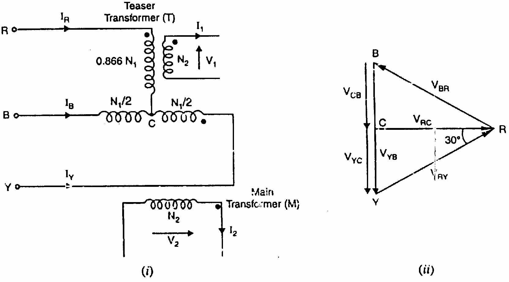
- Main Transformer: Primary connected between lines A and B (VAB), center-tapped at D.
- Teaser Transformer: Primary connected between line C and center-tap D. Its turns are tapped at 23≈86.6% of the main transformer turns.
- Physical Reason for 86.6%: The line-to-midpoint voltage in an equilateral voltage triangle is VCD=23VAB. Tapping at 86.6% turns ensures that the induced volts-per-turn in both transformers are strictly identical.
- Output: Because VCD is perpendicular to VAB, the secondary windings produce two equal voltages displaced by 90° in time, supplying a perfectly balanced 2-phase load.
Q4(b): Numerical Scott Connection (3300V to 440V, 33 kVA Load)
Given Data:
- 3-Phase Line Voltage: V1,L=3300 V
- 2-Phase Load: Sload=33 kVA,V2=440 V balanced across two phases.
1. Secondary Quantities:
- Apparent power per phase: S2=233,000=16,500 VA
- Secondary voltage per phase: V2,main=V2,teaser=440 V
- Secondary current per phase: I2,main=I2,teaser=44016,500=37.50 A
2. Primary Quantities:
- Main Transformer Primary:
- Voltage: V1,main=VAB=3300 V
- Current: I1,main=330016,500=5.00 A
- kVA Rating: 3300 V×5 A=16.50 kVA
- Teaser Transformer Primary:
- Voltage: V1,teaser=23×3300=0.8660×3300=2857.9 V≈2858 V
- Current: Line current from phase C is IC=285816,500=5.77 A
- kVA Rating: 2858 V×5.77 A=16.50 kVA
Q4(c): Transformer Banks and Voltage Ratios for 10:1 Turns Ratio
- Advantages of 3-Phase Transformer Banks:
- Reliability and Service Continuity: If one unit burns out, the remaining two maintain 3-phase service via open-delta (57.7% capacity).
- Modularity and Transport: Three smaller single-phase units are drastically easier to transport into remote mountainous or underground substations than one massive 3-phase tank.
- Spare Strategy: Only one single-phase spare unit needs to be stocked rather than an entire 3-phase spare transformer.
- Line Voltage Ratios (N1:N2=10:1 per phase):
- Y-Y: V2,LV1,L=3V2,ϕ3V1,ϕ=N2N1=10:1
- Δ-Δ: V2,LV1,L=V2,ϕV1,ϕ=N2N1=10:1
- Δ-Y: V2,LV1,L=3V2,ϕV1,ϕ=310:1=5.77:1 (voltage stepped up on secondary)
- Y-Δ: V2,LV1,L=V2,ϕ3V1,ϕ=103:1=17.32:1 (voltage stepped down further)
SECTION - B (Induction Motors: Q5 to Q8)
Question 5
Q5(a): Electrical Braking Techniques in Induction Motors
- Regenerative Braking: Occurs when an external mechanical load drives the motor shaft faster than synchronous speed (N>Ns). Slip becomes negative (s<0), reversing the direction of electromagnetic torque. The machine operates as an induction generator, feeding kinetic energy back into the power lines as electrical power. Highly efficient, used on downhill electric train runs and elevator descents.
- Dynamic (DC Rheostatic) Braking: The stator is disconnected from the 3-phase AC supply and immediately connected to a DC excitation voltage. The DC current sets up a stationary, non-rotating magnetic field in the air gap. As the rotor continues to spin, its conductors cut this stationary field, inducing heavy currents that dissipate rotational kinetic energy as heat in external rotor resistors, bringing the motor smoothly to rest.
- Plugging (Counter-Current Braking): Two stator power leads are swapped while running, abruptly reversing the rotation of the stator RMF. Slip spikes to s=2−sf>1. The motor develops massive reverse torque opposing shaft rotation. To avoid accelerating in the reverse direction, a centrifugal zero-speed switch cuts power the moment speed reaches zero.
Q5(b): Air-Gap Power Proof: Pm=(1−s)P2
See full derivation and tree diagram in IM-01: Air-Gap Power Ratios.
- Total air-gap power transferred into rotor: P2=3I22sR2.
- Rotor copper loss: Pr,Cu=3I22R2=sP2.
- Mechanical power developed internally: Pm=P2−Pr,Cu=P2−sP2=(1−s)P2
- Rotor efficiency: ηrotor=P2Pm=1−s.
Q5(c): Self-Excited Induction Generator (Capacitance and Engine Speed)
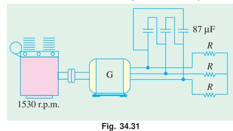
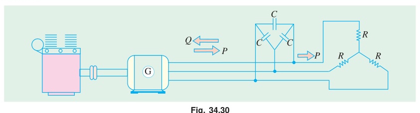
Given Data:
- Rating: 440 V,4-Pole,50 Hz,30 kW,IL=40 A,cosϕ=0.85
- Motoring speed: N=1470 rpm
- Synchronous speed: Ns=4120×50=1500 rpm
1. Terminal Capacitance Per Phase (Delta Connected):
An induction generator cannot self-excite without external reactive VARs to build and sustain air-gap flux:
- Reactive power required: sinϕ=1−(0.85)2=0.5268 Q=3VLILsinϕ=3×440×40×0.5268=16,060 VAR
- Per-phase VAR for Delta capacitors: Qϕ=3Q=316,060=5353.3 VAR
- Capacitive reactance per phase (Vϕ=VL=440 V): XC=QϕVL2=5353.34402=5353.3193,600=36.16Ω
- Capacitance: C=2πfXC1=2π×50×36.161=88.0μF per phase
2. Engine Speed for 50 Hz Output:
- Motor slip: sm=15001500−1470=0.02.
- In generating mode, slip is negative: sgen=−0.02.
- The driving engine must rotate the rotor above synchronous speed: Nengine=Ns(1−sgen)=1500×(1−(−0.02))=1500×1.02=1530 rpm
Question 6
Q6(a): Single-Phasing in 3-Phase Induction Motors
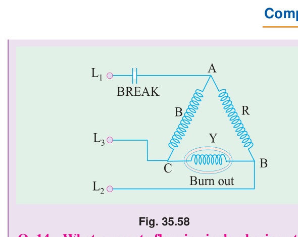
- What Happens at Standstill (Attempting to Start): If one supply line is broken before starting, the motor receives only single-phase power. It develops zero starting torque (Tst=0). The motor will not rotate, drawing extreme locked-rotor current and humming loudly until thermal fuses blow.
- What Happens While Running:
If one line opens while running, the motor continues to spin due to rotational momentum, but the magnetic field collapses into an unbalanced pulsating field.
- Current in the remaining two active lines increases by ≈3×Irated≈173%.
- Rotor slip increases, causing rotor speed to dip.
- The healthy phase windings overheat rapidly; without negative-sequence or thermal overload protection, the stator windings will burn out within minutes.
Q6(b): Proof: Resultant Flux of 3-Phase Induction Motor is Constant (1.5Φm)
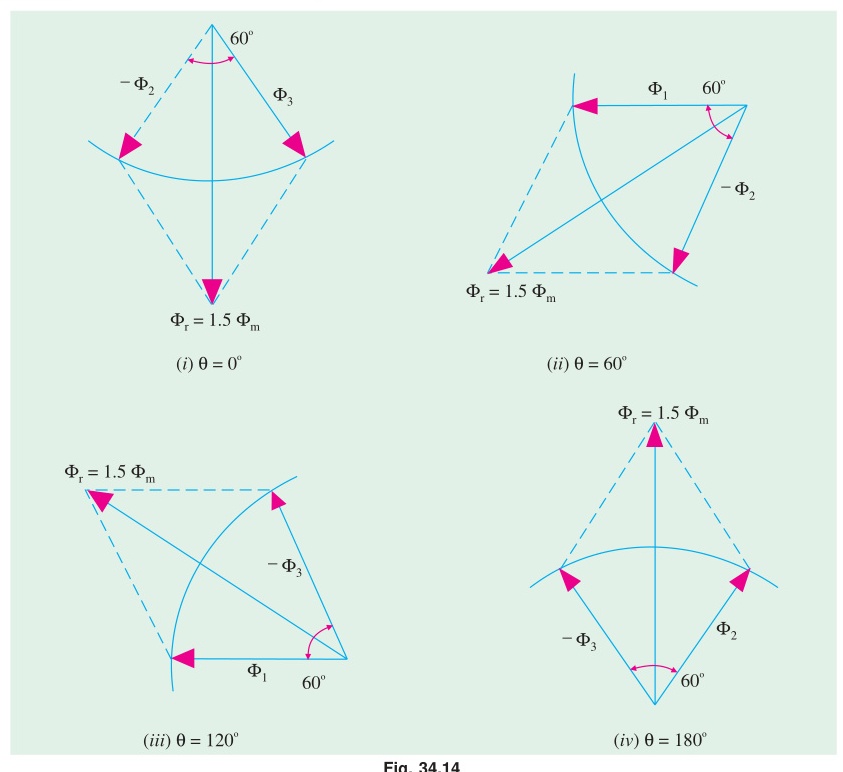
ΦR=Φmsinωt,ΦY=Φmsin(ωt−120°),ΦB=Φmsin(ωt+120°) Resolving along orthogonal spatial axes: Φx=23Φmsinωt,Φy=−23Φmcosωt Φr=Φx2+Φy2=23Φmsin2ωt+cos2ωt=1.5Φm=constant
Q6(c): 6-Pole, 240V IM Numerical Calculation
Given Data:
- Poles P=6,f=50 Hz⟹Ns=1000 rpm,ωs=104.72 rad/s
- Star connection: V1,ϕ=3240=138.56 V
- Turns ratio N1/N2=1.8⟹E2=1.8138.56=76.98 V/phase
- Rotor parameters: R2=0.12Ω,X2=0.85Ω, full-load slip sf=0.04.
1. Full-Load Developed Torque:
k=ωs3=104.723=0.028648 N-m⋅s/W TFL=R22+sf2X22ksfE22R2=(0.12)2+(0.04×0.85)20.028648×0.04×(76.98)2×0.12=0.0144+0.0011560.8146=0.015560.8146=52.35 N-m
2. Maximum Torque:
Tmax=2X2kE22=2×0.850.028648×5925.9=1.70169.76=99.86 N-m
3. Speed at Maximum Torque:
smT=X2R2=0.850.12=0.1412⟹NmT=1000×(1−0.1412)=858.8 rpm
Question 7
Q7(a): Star-Delta Starter Operation and Trade-Offs
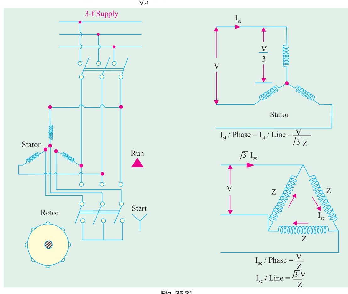
- Mechanism:
- Starting (Star): Phase voltage is reduced to Vϕ=3VL. Line starting current is reduced to Ist,star=31Ist,delta, and starting torque drops to Tst,star=31Tst,delta.
- Running (Delta): Once the motor reaches ~80% speed, a timer or centrifugal switch snaps the contacts to Delta, restoring full rated line voltage across each phase winding.
- Limitation: The 67% reduction in starting torque makes it unsuitable for high-inertia or heavy loaded starting (e.g., loaded crushers, positive displacement pumps).
Q7(b): Circle Diagram Graphical Analysis (5.6 kW Slip-Ring IM)
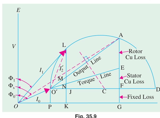
- Scaled SC Current at Rated 400 V: Isc=12×100400=48 A.
- Loss Separation: Stator copper loss is calculated from measured R1, dividing the vertical short-circuit line into stator Cu loss and rotor Cu loss segments.
- Reading at Rated Output (5.6 kW):
- Full-load line current ≈10.5 A
- Full-load operating slip ≈6.2%
- Full-load power factor ≈0.78 lagging
- Maximum mechanical power output ≈8.2 kW
Question 8
Q8(a): Double-Field Revolving Theory of Single-Phase IM
See comprehensive derivation in IM-03: Single-Phase Induction Motor: Double Revolving Field Theory.
- Forward field Φf=Φm/2 at +Ns with slip sf=s.
- Backward field Φb=Φm/2 at −Ns with slip sb=2−s.
- At standstill (s=1), torques cancel exactly (Tf=Tb⟹Tnet=0).
Q8(b): Resistor Split-Phase Motor Starting Condition
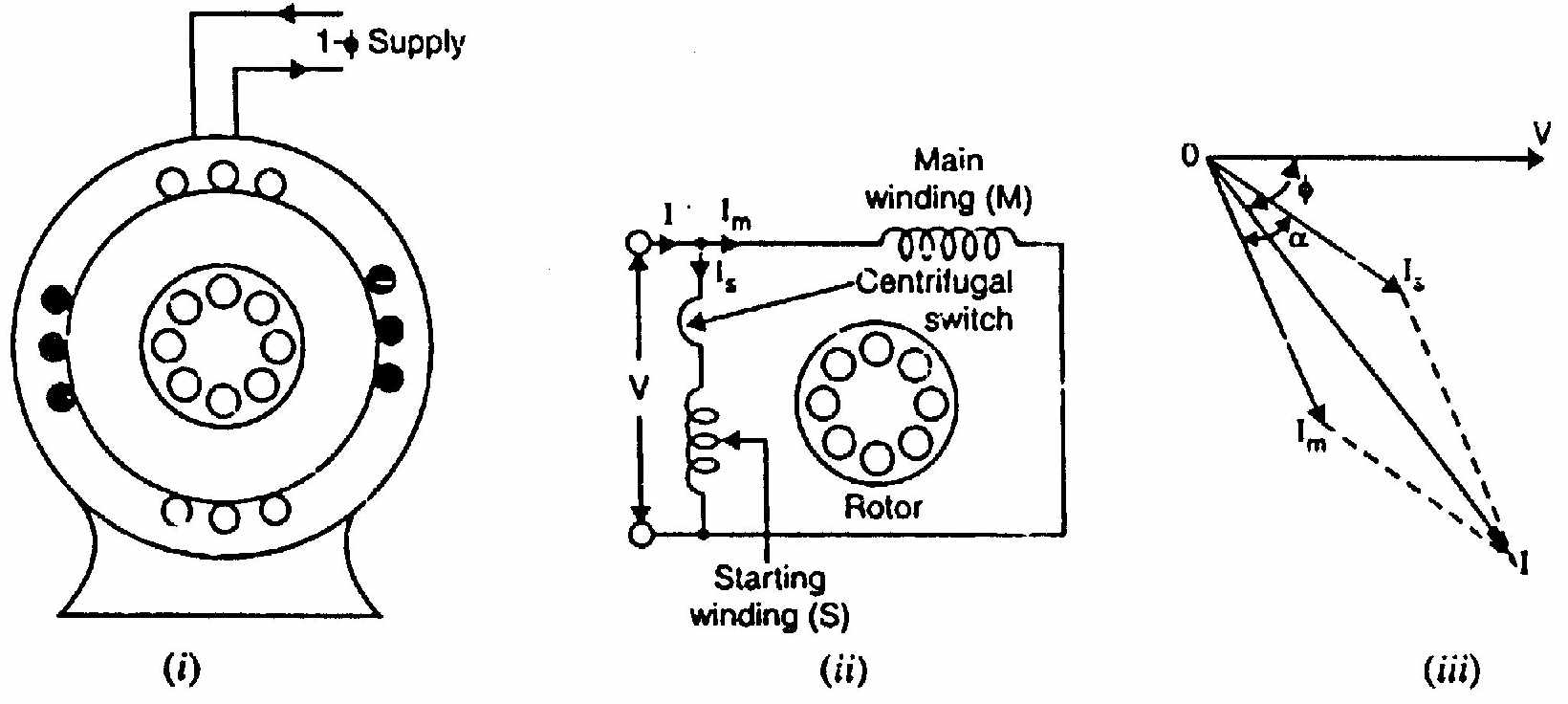
In a resistance split-phase motor, the auxiliary winding is wound with finer wire (high resistance, low reactance), while the main winding has thick wire (low resistance, high reactance).
- For maximum starting torque, the two currents must be in temporal quadrature (ϕm−ϕa=90°).
- Matching the winding impedance angles and effective turns ratio (Na/Nm) yields the optimum auxiliary resistance design formula: ra=(NmNa)2(rm+zm)
Q8(c): Capacitor Calculation for Maximum Starting Torque
Given Data:
- Main winding: V=100 V,I=2 A,P=40 W⟹Zm=2100=50Ω,Rm=2240=10Ω,Xm=502−102=48.99Ω ϕm=cos−1(5010)=78.46° lagging
- Auxiliary winding: V=80 V,I=1 A,P=50 W⟹Za=80Ω,Ra=1250=50Ω,Xa=802−502=62.45Ω
Condition for 90° Quadrature:
For auxiliary current to lead main current by 90°, it must lead the supply voltage by: ϕa=90°−78.46°=11.54° leading tan(11.54°)=RaXC−Xa=50XC−62.45=0.20416 XC−62.45=50×0.20416=10.21Ω XC=62.45+10.21=72.66Ω C=2πfXC1=2π×50×72.661=22,826.91=43.8μF
Source: PrevYearQuestions/2018.md