CT_Questions/CT_answers_exam_style.md
10.0 KB · commit d2f3b6e
← CT-04 | 🏠 Index | CT Explanations →
ECE 2207: Electrical Machines I
CT Questions: All Answers: Exam Style
Department: ECE, RUET | Session: 2023-24
How to use this file: Concise, exam-ready answers. Every key step is present without extra commentary. Focus on structure and critical equations.
CT-01 (19/07/2026): Induction Motors
Q1. Prove that 3-φ stator flux rotates at synchronous speed. [10 Marks]
Setup: Three windings 120° apart in space. Balanced 3-phase supply gives:
ΦR=Φmsin(ωt),ΦY=Φmsin(ωt−120°),ΦB=Φmsin(ωt+120°)
At four key instants:
| ωt | Φ_R | Φ_Y | Φ_B | Resultant |
|---|---|---|---|---|
| 0° | 0 | −(√3/2)Φ_m | +(√3/2)Φ_m | 1.5Φ_m ↑ |
| 60° | +(√3/2)Φ_m | −(√3/2)Φ_m | 0 | 1.5Φ_m (60° rotated) |
| 120° | +(√3/2)Φ_m | 0 | −(√3/2)Φ_m | 1.5Φ_m (120° rotated) |
| 180° | 0 | +(√3/2)Φ_m | −(√3/2)Φ_m | 1.5Φ_m (180° rotated) |
General proof (component method):
Resolve along X and Y axes:
Φx=23Φmsin(ωt),Φy=−23Φmcos(ωt)
Magnitude: Φr=Φx2+Φy2=23Φm=1.5Φm(constant)
Space angle: θ=ωt−90°, so dtdθ=ω=2πf
Ns=P120f rpm
Conclusion: Resultant flux = 1.5Φm (constant magnitude), rotates at synchronous speed Ns. (Proved)
Q2. Explain the basic operating principle of an induction motor. [10 Marks]
-
RMF is produced. 3-phase supply creates a rotating magnetic field of constant magnitude 1.5Φm at speed Ns=P120f.
-
Field cuts rotor bars. At start N=0, relative speed =Ns. The rotating field sweeps across stationary rotor conductors.
-
EMF is induced. By Faraday's Law, e=Blvrel is induced in each rotor bar.
-
Rotor current flows. End rings (squirrel cage) or external resistors (wound rotor) close the circuit. Induced EMF drives rotor current.
-
Torque is developed. By Lorentz force law, F=BIl acts on current-carrying bars inside the stator field.
-
Rotor spins (Lenz's Law). Rotor turns in the same direction as the RMF to reduce relative motion.
-
Cannot reach Ns. If N=Ns: relative speed = 0 → EMF = 0 → current = 0 → torque = 0. Friction slows the rotor. Always N<Ns.
s=NsNs−N,fr=sf
CT-02 (03/08/2026): Induction Motors
Q1. Justify: Maximum torque is independent of R₂. [10 Marks]
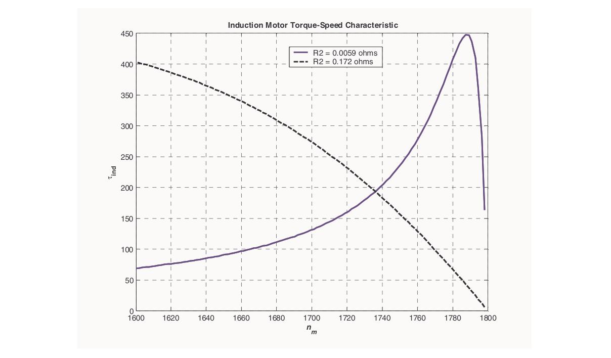
Torque equation: T=R22+s2X22k⋅sE22R2,k=2πNs3
Slip at max torque: Differentiate w.r.t. s, set to zero:
dsdT=0⟹R22−s2X22=0⟹smT=X2R2
Peak slip depends on R2. Increasing R2 shifts the torque peak to higher slip.
Value of Tmax: Substitute s=R2/X2:
Tmax=R22+X22R22⋅X22k⋅X2R2⋅E22⋅R2=2R22k⋅X2R22⋅E22=2X2kE22
R2 cancels completely. Tmax depends only on E2 (supply voltage) and X2 (standstill reactance).
Conclusion:
- Changing R2 shifts peak position (smT=R2/X2) but not peak value.
- At R2=X2: smT=1, so maximum torque coincides with starting torque. (Justified)
Q2. Explain the blocked rotor test of an induction motor. [10 Marks]
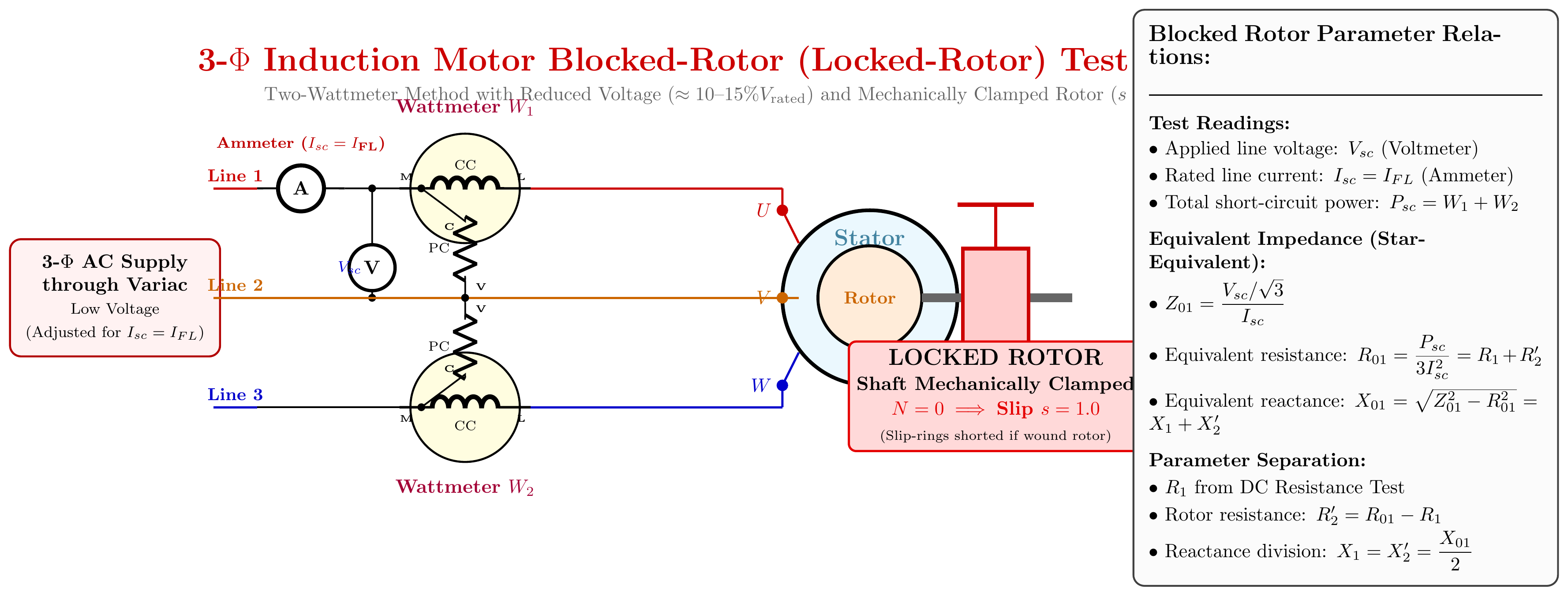
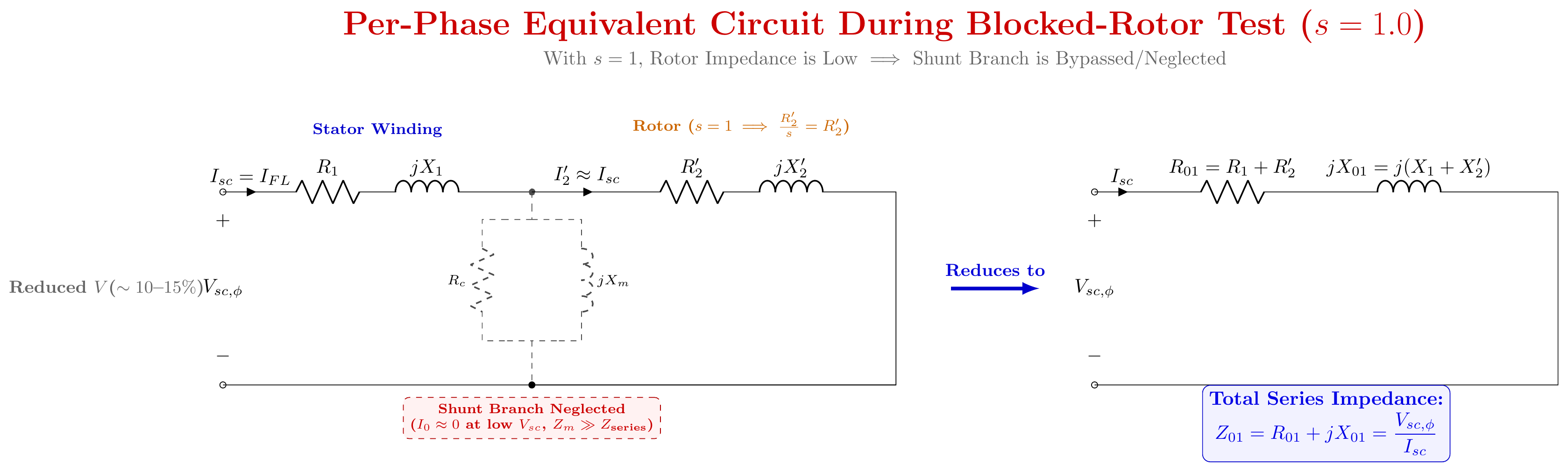
Setup: Rotor is locked (N=0, s=1). Analogous to the short-circuit test of a transformer.
Circuit:
3-φ Supply → Variac → [V, A, W1+W2] → Stator terminals
                                        [Rotor: LOCKED]
Procedure:
- Lock the rotor mechanically.
- Short-circuit slip rings (wound rotor).
- Start with zero voltage. Raise via variac until rated stator current flows.
- Record: Vbr, Ibr, Pbr=W1+W2.
Why low voltage? Core loss ∝ V2. At 10–15% rated voltage, iron loss ≈ 0. So Pbr = copper losses only.
Parameters (star-connected): Z01=IbrVbr/3,R01=3Ibr2Pbr,X01=Z012−R012 R2′=R01−R1,X1≈X2′=2X01
Necessities:
- Gives full-load copper loss → efficiency calculation.
- Gives R01, X01 → series branch of equivalent circuit.
- Starting current at rated voltage: Isc=Ibr×(Vrated/Vbr).
- Estimates starting torque: Tst∝Isc2R2.
- Needed for circle diagram construction (gives cosϕsc and Isc).
CT-03 (26/08/2026): Transformers
Q1. Schematic of a 1-φ transformer with variables labeled. [10 Marks]
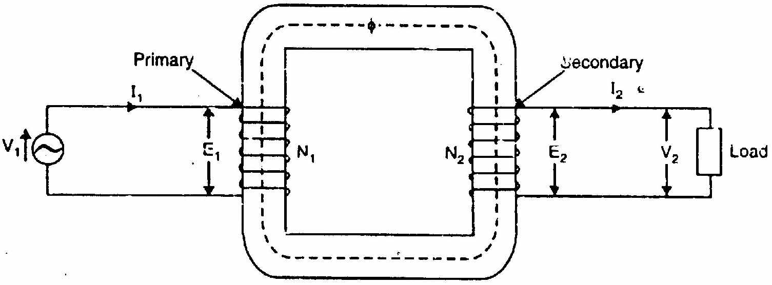
Primary variables:
| Symbol | Meaning |
|---|---|
| v1(t), V1 | Applied terminal voltage (instantaneous / RMS) |
| i1(t), I1 | Primary current from AC source |
| N1 | Number of primary turns |
| e1(t), E1 | Self-induced counter-EMF (lags Φ by 90°) |
Secondary variables:
| Symbol | Meaning |
|---|---|
| N2 | Number of secondary turns |
| e2(t), E2 | Mutually induced EMF |
| v2(t), V2 | Secondary terminal voltage |
| i2(t), I2 | Load current |
| ZL=RL+jXL | Load impedance |
Core variables:
| Symbol | Meaning |
|---|---|
| Φ(t) | Instantaneous mutual flux (Wb) |
| Φm | Peak mutual flux (Wb) |
| A | Core cross-sectional area (m²) |
| K=N2/N1 | Voltage transformation ratio |
Q2. Prove E1=4.44fN1Φm and E2=4.44fN2Φm. [10 Marks]
Given: Φ(t)=Φmsin(ωt). Same flux links both windings (no leakage).
Derivation for E1:
By Faraday's Law: e1(t)=−N1dtdΦ=−N1ωΦmcos(ωt)=N1ωΦmsin(ωt−90°)
Peak value: Em1=N1ωΦm=2πfN1Φm
RMS value: E1=2Em1=22πfN1Φm=2πfN1Φm
Since 2π=4.44:
E1=4.44fN1Φm
For E2: Same flux, same derivation with N2:
E2=4.44fN2Φm(Proved)
Alternative (average EMF method): In quarter-cycle T/4=1/(4f), flux changes by Φm: Average EMF/turn=4fΦm Erms=Kf×4fΦm=1.11×4fΦm=4.44fΦm Multiply by turns: E1=4.44fN1Φm, E2=4.44fN2Φm (Same result)
CT-04 (09/09/2026): Transformers
Q1. Effect of leakage flux on transformer operation (with schematic). [10 Marks]
Three types of flux:
- Φm: mutual flux, links both windings through core, transfers power.
- Φl1: primary leakage flux, links only N1 turns, path through air.
- Φl2: secondary leakage flux, links only N2 turns, path through air.
Schematic:
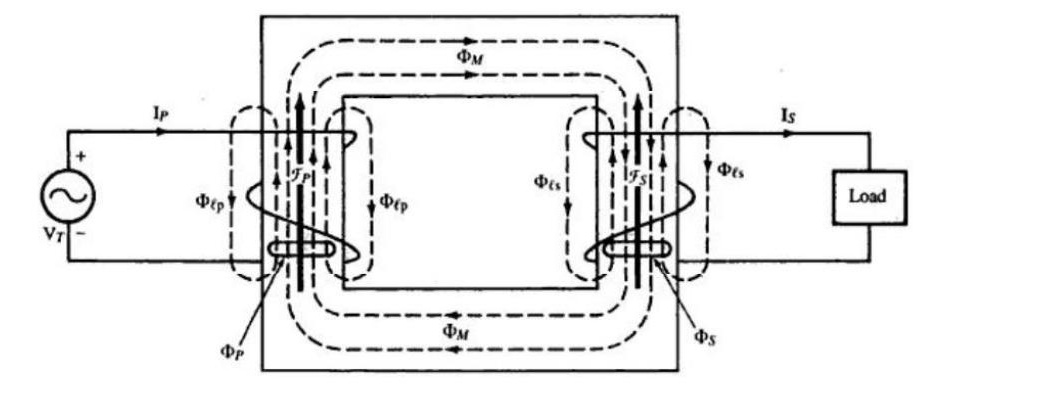
Effects:
-
Leakage reactances: Each leakage flux induces a self-EMF lagging by 90°. This behaves like a series reactance: X1=2πfLl1,X2=2πfLl2
-
Voltage drop inside windings: V1=−E1+I1R1+jI1X1 V2=E2−I2R2−jI2X2
-
Worse voltage regulation: Under lagging pf loads, jI2X2 reduces V2.
-
Fault current limiting (beneficial): During a short circuit, X1+X2 limits the fault current and protects the transformer.
Q2. Phasor diagram of an R-L loaded ideal transformer: step by step. [10 Marks]
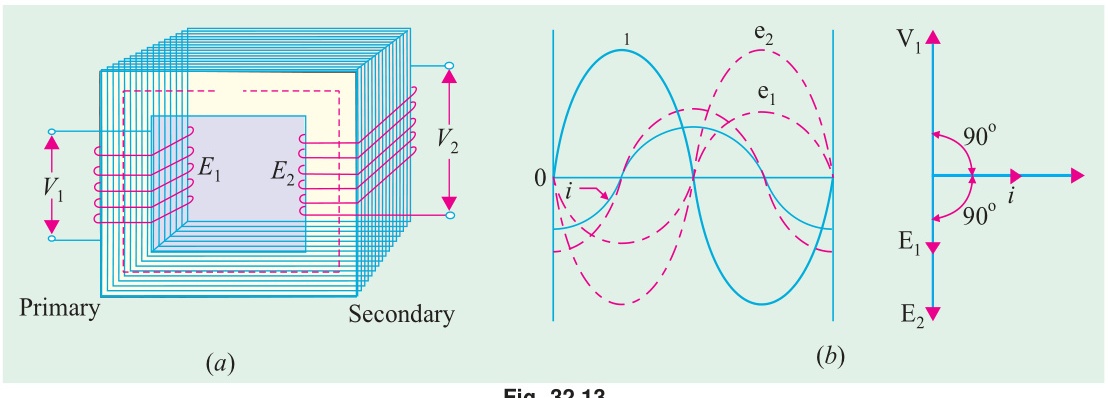
Ideal transformer assumptions: R1=R2=X1=X2=0, I0=0, so V2=E2 and V1=−E1.
Step 1: Reference phasor: Draw Φm along the +X axis (horizontal reference).
Step 2: Induced EMFs: By Faraday's Law, induced EMF lags flux by 90°. Draw E1 and E2 vertically downward (−Y axis).
Step 3: Secondary terminal voltage: No internal drops in ideal transformer. V2=E2 (downward).
Step 4: Secondary load current: R-L load, so I2 lags V2 by θ2=tan−1(XL/RL). Draw I2 clockwise from V2.
Step 5: Primary current: Ampere-turn balance: N1I1=N2I2. Primary current is opposite to I2: I1=−N1N2I2(180° reversed)
Step 6: Primary voltage: No drops. V1=−E1 (vertically upward, +Y axis).
Step 7: Power factor angle: Angle between V1 and I1 equals θ1=θ2. Same pf on both sides.
Phasor summary:
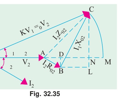
| Phasor | Angle |
|---|---|
| Φm | 0° |
| E1=E2=V2 | −90° |
| V1 | +90° |
| I2 | −90°−θ2 |
| I1 | 90°−θ1 (= 90°−θ2) |
Source questions: CT_01.md · CT_02.md · CT_03.md · CT_04.md