CT_Questions/CT_02.md
9.0 KB · commit d2f3b6e
Department of Electrical & Computer Engineering (ECE), RUET
2nd Year Even Semester (Session 2023-24)
Class Test (CT) Questions — CT-02
Course Code: ECE 2207
Course Title: Electrical Machines-I
Date: 03/08/2026
Time: 20 minutes
Total Marks: 20 (10 marks per question)
Question Paper Scan
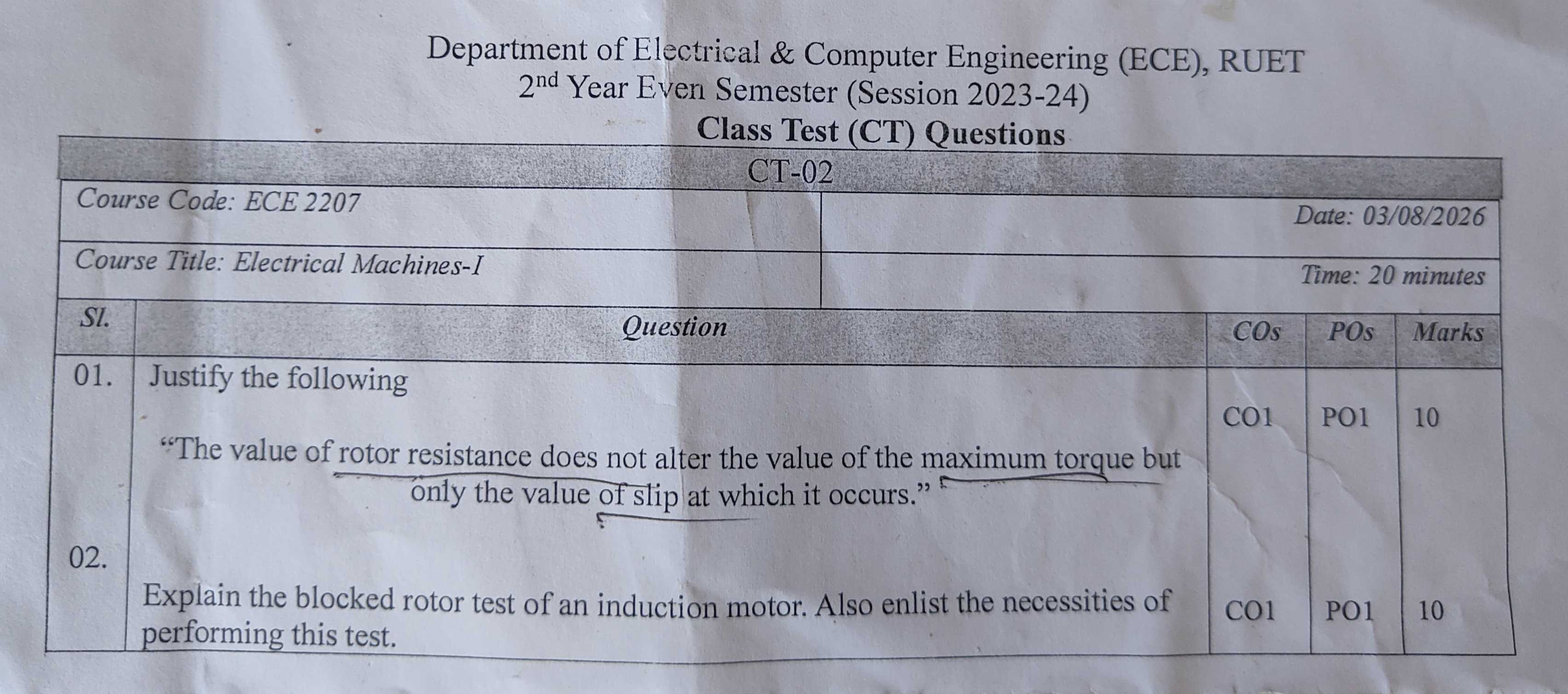
Question Paper Transcript
| Sl. | Question | COs | POs | Marks |
|---|---|---|---|---|
| 01. | Justify the following: "The value of rotor resistance does not alter the value of the maximum torque but only the value of slip at which it occurs." | CO1 | PO1 | 10 |
| 02. | Explain the blocked rotor test of an induction motor. Also enlist the necessities of performing this test. | CO1 | PO1 | 10 |
Comprehensive Solutions & Analysis
Question 01: Maximum Torque and Rotor Resistance Independence
Statement to Justify: "The value of rotor resistance does not alter the value of the maximum torque but only the value of slip at which it occurs." [Marks: 10, CO: 1, PO: 1]
1. Mathematical Derivation of Rotor Torque
Let:
- E2 = Rotor induced EMF per phase at standstill
- X2 = Standstill rotor leakage reactance per phase
- R2 = Rotor circuit resistance per phase
- s = Operating slip of the motor
At any running slip s:
- Induced rotor EMF per phase: E2s=sE2
- Rotor leakage reactance per phase: X2s=sX2
- Rotor impedance per phase: Z2s=R22+(sX2)2
The rotor current per phase is: I2=R22+(sX2)2sE2
The rotor power factor is: cosθ2=Z2sR2=R22+(sX2)2R2
The developed electromagnetic torque is proportional to the rotor power input: T=kt⋅E2⋅I2⋅cosθ2 T=R22+s2X22k⋅sE22R2
Here k=2πNs3 is a machine constant.
2. Slip for Maximum Torque (smT)
To find the slip at which torque reaches its peak, differentiate T with respect to slip s and set it to zero: dsdT=0
Using the quotient rule: dsd[R22+s2X22sR2]=(R22+s2X22)2(R22+s2X22)(R2)−(sR2)(2sX22)=0
Set the numerator to zero: R2(R22+s2X22)−2s2R2X22=0 R22−s2X22=0 s2=X22R22 smT=X2R2
This shows that the slip at maximum torque smT is directly proportional to rotor resistance R2: smT∝R2
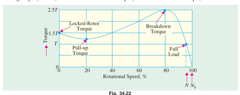
If rotor resistance increases, maximum torque occurs at a higher slip (a lower rotor speed).
3. Value of Maximum Torque (Tmax)
Substitute the condition s=smT=X2R2 into the general torque equation:
Tmax=R22+(X2R2)2X22k(X2R2)E22R2 Tmax=R22+R22k(X2R22)E22=2R22k(X2R22)E22 Tmax=2X2kE22
4. Physical Justification & Conclusion
- Tmax is independent of R2: The term R2 cancels out completely from the final expression for Tmax. Maximum torque depends only on supply voltage (E2∝V) and standstill rotor leakage reactance X2.
- Peak position shifts with R2: The slip at which the peak occurs is smT=X2R2. Adding external resistance to the rotor circuit shifts the torque peak toward higher slip (lower speed).
- Starting torque improves: If we insert external rotor resistance such that R2=X2, then smT=1. The motor develops its maximum possible torque right at start (N=0).
- Summary: Varying rotor resistance changes the location of the maximum torque on the speed axis. But it never alters the magnitude of the peak itself. (Justified)
Question 02: Blocked Rotor Test of an Induction Motor
Question: Explain the blocked rotor test of an induction motor. Also enlist the necessities of performing this test. [Marks: 10, CO: 1, PO: 1]
1. Test Description & Operating Setup
The blocked rotor test is analogous to the short-circuit test of a transformer. The rotor is held stationary so that it cannot rotate (N=0, slip s=1).
3-Phase AC    3-Phase        Wattmeters      Stator Terminals
Supply -----> Variac -------> [ W1, W2 ] ------> [ A1, B1, C1 ]
                              Ammeters [A]
                              Voltmeter [V]        Rotor Shaft
                                                    [ LOCKED / BLOCKED ]
Procedure:
- Lock the rotor shaft mechanically using a clamp or brake band so it cannot rotate.
- Short-circuit the slip rings if using a wound rotor motor.
- Connect a three-phase autotransformer (variac) to the stator through a voltmeter, ammeters, and two wattmeters.
- Start with zero applied voltage.
- Gradually increase the voltage until rated full-load stator current flows through the ammeters.
- Record the applied line voltage Vbr, line current Ibr, and total input power Pbr=W1+W2.
- Keep the test brief to avoid overheating the rotor and stator windings.
Why Core Loss is Neglected:
The applied voltage Vbr during this test is small. It is typically only 10% to 15% of rated line voltage. Core loss is proportional to voltage squared (V2). Because the test voltage is very low, the iron losses in the stator and rotor are negligible. The measured input power Pbr is taken entirely as full-load copper loss of both windings.
2. Parameter Calculations
Assuming a star-connected stator:
-
Per-phase values: Vphase=3Vbr,Iphase=Ibr
-
Total equivalent impedance referred to stator: Z01=IbrVbr/3
-
Total equivalent resistance referred to stator: Pbr=3⋅Ibr2⋅R01⟹R01=3Ibr2Pbr
-
Total equivalent leakage reactance referred to stator: X01=Z012−R012
-
Separating stator and rotor parameters: Measure DC resistance of stator winding R1,dc and multiply by 1.2 to 1.3 for AC skin effect to get R1. The rotor resistance referred to stator is: R2′=R01−R1 The leakage reactance is usually split equally: X1=X2′=0.5X01
3. Necessities of Performing the Blocked Rotor Test
The blocked rotor test is necessary for the following engineering reasons:
- Measurement of Full-Load Copper Losses: It gives the total I2R loss of the stator and rotor windings at rated current. This is required to determine motor efficiency.
- Extraction of Equivalent Circuit Series Parameters: It supplies R01, X01, and Z01. These values form the series branch of the exact and approximate equivalent circuits.
- Calculation of Short-Circuit Current at Rated Voltage: Because impedances are linear, the starting current with full rated voltage applied across the terminals is: Isc=Ibr×(VbrVrated)
- Estimation of Starting Torque: Starting torque depends directly on short-circuit current and rotor resistance (Tst∝Isc2R2). The test values help determine starting torque without running the motor at full voltage.
- Construction of Circle Diagram: The short-circuit power factor cosϕsc=3VbrIbrPbr and short-circuit current Isc are needed to draw the short-circuit line and complete the circle diagram of the induction motor.
Cross-References & Study Vault Links
- Classroom Board Notes on Torque Derivation: ClassNoteByRaidah/Class_07.md
- Classroom Board Notes on Maximum Torque: ClassNoteByRaidah/Class_08.md
- Classroom Notes on Motor Testing: ClassNoteByRaidah/Class_09.md
- Faculty Lecture Slides: SlidesByMaam/L-03_ECE-2107.md, SlidesByMaam/L-04_ECE-2107.md
- Textbook Chapter: Books/B.L._Theraja/Ch-34_Induction_Motor.md, Books/B.L._Theraja/Ch-35_Computation_and_Tests_on_Induction_Motors.md
- Semester Final Repeats: PrevYearQuestions/2023.md, PrevYearQuestions/2020.md