ClassNoteByRaidah/Class_09_Induction_Motor_Testing.md
5.3 KB · commit d2f3b6e
| class | 09 |
|---|---|
| date | 21.07.2026 / 22.07.2026 |
| instructor | Fariya Tabassum (FT Mam) |
| course | ECE-2207: Electrical Machines-I |
| student | Raidah (Roll: 2310035) |
| scan_pages | 017, 018, 019 |
| notebook_pages | 17_R, 18_L, 18_R, 19_L |
| topics | Purpose of Induction Motor Testing (Parameter Extraction), {"The Three Essential Tests":"No-Load, Blocked Rotor, DC Test"}, Two-Wattmeter Measurement Circuit, No-Load (Open-Circuit) Test Formulation, Blocked-Rotor (Short-Circuit) Test Formulation, DC Stator Resistance Test (Wye vs Delta Conversions) |
Class 09: Induction Motor Testing — No-Load, Blocked Rotor & DC Tests
Date: 21.07.2026 / 22.07.2026 | Instructor: Fariya Tabassum (FT Mam)
Source Scan Pages: P17_R, P18 (Left/Right), P19_L
← Previous Class: Class 08 | 📚 Index | Next Class: Class 10 →
1. Overview and Purpose of Testing
The primary objective of induction motor testing is to experimentally determine the essential parameters of the per-phase equivalent circuit (R1,X1,R2,X2,Xm,Rc):
Parameter Determination⟶X1,R1,X2,R2,Xm
The Three Interdependent Tests
├── 1. No-Load Test (Open-Circuit Test)      ──> Core loss, friction/windage loss, X_m
├── 2. Blocked-Rotor Test (Short-Circuit)    ──> Equivalent leakage reactance (X_1 + X_2), (R_1 + R_2)
└── 3. DC Resistance Test                   ──> Stator per-phase winding resistance R_1
- Grid and Voltage Ratings:
- Industrial and commercial 3-phase supply: VL=400 V (Line-to-Line).
- Residential single-phase voltage: Vp=3VL=3400≈230 V (Phase-to-Neutral).
2. No-Load (Open Circuit) Test
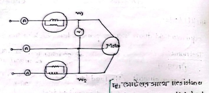
- Test Condition:
- No mechanical load is coupled to the motor shaft (Load=0).
- The rotor accelerates to near-synchronous speed (Nr≈Ns).
- Consequently, slip is extremely small / near zero: s≈0⟹sR2⟶∞
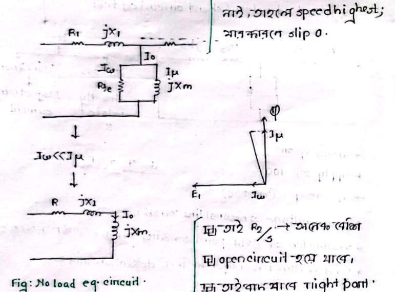
Circuit Simplification:
- Since sR2≈∞, the parallel rotor branch acts virtually as an Open Circuit.
- Furthermore, Iw≪Iμ (the wide air-gap requires a dominant magnetizing current).
- Therefore, the total input power measured by wattmeters comprises: PNL=3INL2R1+Pcore+Pw,f (Stator copper loss + Core iron loss + Friction and windage losses).
3. Blocked Rotor (Locked Rotor) Test
- Test Condition:
- The rotor is mechanically clamped/locked so that it cannot rotate: Nr=0⟹s=NsNs−0=1
- A very low reduced voltage (10−15% of rated voltage) is applied to the stator to circulate rated full-load current.
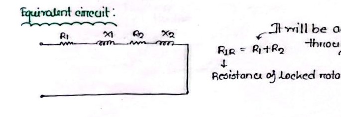
Circuit Simplification:
- Since s=1, the effective rotor resistance is sR2=R2 (which is very small).
- Due to the drastically reduced applied voltage, current through the parallel magnetizing branch (Xm,Rc) is negligible (I0≈0).
- The entire network simplifies into a simple series circuit: ZBL=IBLVBL/3 RBL=R1+R2=3IBL2PBL XBL=X1+X2=ZBL2−RBL2 (Typically divided equally: X1=X2=0.5XBL).
4. DC Stator Resistance Test
When DC is applied to an inductive coil, the inductive reactance drops to zero (ω=0⟹XL=0). The inductor behaves as a pure short circuit, leaving only the pure ohmic resistance effective:
RDC=IDCVDC (Total DC resistance measured between any two line terminals).
Relation Between RDC and Per-Phase Stator Resistance (R1):
-
For Wye / Star (Y) Connected Stator: Two phase windings are connected in series: RDC=2R1⟹R1(wye)=2RDC
-
For Delta (Δ) Connected Stator: One phase winding is connected in parallel with the series combination of the other two phases: RDC=R1∥(R1+R1)=3R1R1⋅2R1=32R1 ⟹R1(Δ)=1.5⋅RDC
← Previous Class: Class 08 | 📚 Back to Index | Next Class: Class 10 →