SlidesByMaam/L-03_ECE-2107.md
11.8 KB · commit d2f3b6e
Electrical Machines-I
ECE-2107
Induction Motor-SL2
Fariya Tabassum
Assistant Professor, Dept. of Electrical & Computer Engineering
Rajshahi University of Engineering & Technology, Rajshahi-6204
“Verily, with every difficulty there is relief”.
[Sura Ash-Sharh]
Synchronous Speed
In motor, the speed of the rotating flux is called synchronous speed. Depending on the motor design, the actual mechanical speed may be same (synchronous motor) or slightly smaller (asynchronous motor). It is directly proportional to the supply frequency and inversely proportional to the number of pairs of poles. As poles occur in pair, its mathematical expression is
ns=P/2fs=P2×fsr/s
ns=P120×fsr/min
Why Does the Rotor Rotate
The operating principle of the 3-φ induction motor can be explained as follows:
- When 3-phase stator winding is energized from 3-phase supply, a rotating magnetic field is set up which rotates round the stator at synchronous speed Ns (= 120 f/P).
- The rotating field passes through the air gap and cuts the rotor conductors, which as yet, are stationary. Due to the relative speed between the rotating flux and the stationary rotor, e.m.f.s are induced in the rotor conductors. Since the rotor circuit is short-circuited, currents start flowing in the rotor conductors.
Why the Rotor Rotates
- The current-carrying rotor conductors are placed in the magnetic field produced by the stator. Consequently, mechanical force acts on the rotor conductors. The sum of the mechanical forces on all the rotor conductors produces a torque which tends to move the rotor in the same direction as the rotating field.
- The fact that rotor is urged to follow the stator field (i.e., rotor moves in the direction of stator field) can be explained by Lenz’s law. According to this law, the direction of rotor currents will be such that they tend to oppose the cause producing them. Now, the cause producing the rotor currents is the relative speed between the rotating field and the stationary rotor conductors. Hence to reduce this relative speed, the rotor starts running in the same direction as that of stator field and tries to catch it.
Rotor Slip
Two terms are commonly used for defining the relative motion of the rotor and the magnetic fields. One is slip speed and other is slip.
The difference between the synchronous speed of the rotating flux and the speed of the rotor is called slip speed.
nslip=nsync−nr
where: nslip= slip speed of machine (r/min)
nsync= synchronous speed of the magnetic fields
nr= rotor speed (r/min)
Rotor Slip
The ratio of the sleep speed to synchronous speed is called slip. It is expressed in per-unit or percentage basis.
s=nsyncnslip(×100%)
s=nsyncnsync−nr(×100%)
If the rotor turns at synchronous speed, then s=0, while if the rotor is stationary, then s=1. so, all the normal speed falls between these two limits. Now, the rotor (motor) speed can be written as
nr=nsync(1−s)
Frequency of Rotor Current
Let at any slip-speed, the frequency of the rotor current be, fr. Then,
nsync−nr=P120fr(1)
Also, nsync=P120f(2)
By dividing equation (1) by (2)
ffr=nsyncnsync−nr=s
fr=sf
Relation between supply frequency and rotor current frequency
When the rotor is stationary (s=1), the frequency of rotor current is same as the supply frequency.
For preparing your answer go through the article 34.11 of the book written by “B. L. Theraza”
Problems
Practice example 34.3, 34.4, 34.5 of B. L. Theraza and also the related tutorial problem.
Vector Diagram of Induction Motor
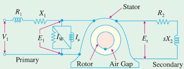
The transfer of energy from stator to the rotor of an induction motor takes place entirely inductively, with the help of a flux mutually linking the two. Hence, an induction motor is essentially a transformer with stator forming the primary and rotor forming (the short-circuited) rotating secondary and the vector diagram is similar to that of a transformer.
Vector Diagram of Induction Motor
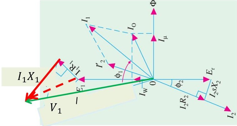
In the vector diagram V1 is the applied voltage per stator phase, R1 and X1 are the stator resistance and leakage reactance per phase respectively. The applied voltage V1 produces a magnetic flux which links both primary and secondary thereby producing an e.m.f E1 at primary and a mutually induced e.m.f. Er at secondary. There is no secondary terminal voltage V2 in secondary because whole of the induced e.m.f is used up in circulating the rotor current as the rotor is closed upon itself (equivalent to its being short-circuited).
Now
V1=E1+I1R1+jI1X1
And
Er=I2Z2=I2(R2+jsX2)
Vector Diagram of Induction Motor
In the vector diagram I0 is the no-load primary current. It has two components (i) the working or iron loss component, Iw and (ii) the magnetizing component, Iμ.
Obviously I0=(Iw2+Iμ2)
For preparing your answer you can go through the article 34.47 of the book written by “B. L. Theraza”
Equivalent Circuit of Induction Motor
Before proceeding recall that an induction motor can be treated as a rotating transformer, i. e., one in which primary winding is stationary but the secondary is free to rotate.
The Transformer Model of an Induction Motor:
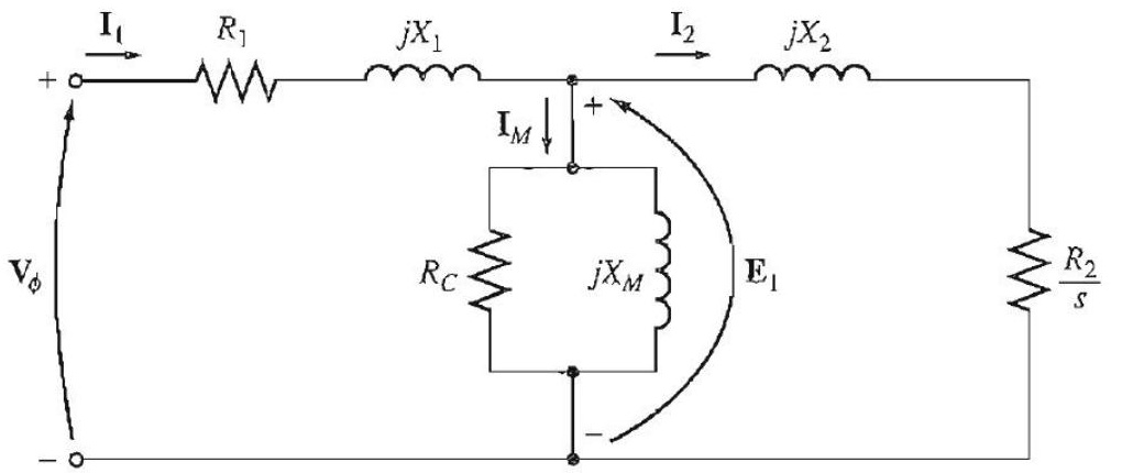
A transformer (per-phase) equivalent circuit, representing the operation of an induction motor is sown in above figure. As in any transformer, there is a certain resistance and self-inductance in the primary (stator) windings, which must be represented in the equivalent circuit of the machine. The stator resistance will be called R1, and the stator leakage reactance will be called X1. These two components appear right at the input to the machine model.
Equivalent Circuit of Induction Motor
Also, like any transformer with an iron core, the flux in the machine is related to the integral of the applied voltage E1.
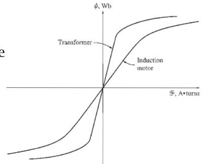
The curve of magnetomotive force versus flux (magnetization curve) for this machine is compared to a similar curve for a power transformer in the figure. Here, the slope of the induction motor's magnetomotive force-flux curve is much shallower than the curve of a good transformer. This is Because there must be an air gap in an induction motor, which greatly increases the reluctance of the flux path and therefore reduces the coupling between primary and secondary windings. The higher reluctance caused by the air gap means that a higher magnetizing current is required to obtain a given flux level. Therefore, the magnetizing reactance XM in the equivalent circuit will have a much smaller value than it would in an ordinary transformer.
Equivalent Circuit of Induction Motor
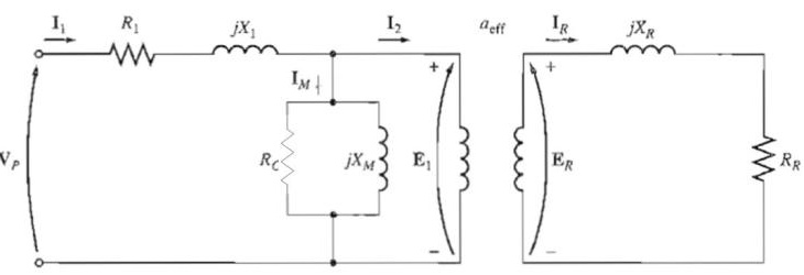
Also, The primary internal stator voltage E1 is coupled to the secondary ER by an ideal transformer with an effective turns ratio. The voltage ER produced in the rotor in turn produces a current which flows in the shorted rotor (or secondary) circuit of the machine. The primary impedances and the magnetization current of the induction motor are very similar to the corresponding components in a transformer equivalent circuit.
An induction motor equivalent circuit differs from a transformer equivalent circuit primarily because of the rotating secondary (rotor) which have slip.
Equivalent Circuit of Induction Motor
Rotor circuit model
In an induction motor, when the voltage is applied to the stator windings, a voltage is induced in the rotor windings of the machine. In general, the greater the relative motion between the rotor and the stator magnetic fields, the greater the resulting rotor voltage and rotor frequency. The largest relative motion occurs when the rotor is stationary (slip=1), called the locked-rotor or blocked-rotor condition, so the largest voltage and rotor frequency are induced in the rotor at that condition. The smallest voltage (0 V) and frequency (0 Hz) occur when the rotor moves at the same speed as the stator magnetic field, resulting in no relative motion. The magnitude and frequency of the voltage induced in the rotor at any speed between these extremes is directly proportional to the slip of the rotor.
Equivalent Circuit of Induction Motor
If the magnitude of the induced rotor voltage at locked-rotor conditions is called ER0, the magnitude of the induced voltage at any slip will be given by the equation
ER=sER0
and the frequency of the induced voltage at any slip will be given by the equation
fr=sf
This voltage is induced in a rotor containing both resistance and reactance. The rotor resistance RR is a constant (except for the skin effect), independent of slip, while the rotor reactance is affected in a more complicated way by slip. With a rotor inductance of LR, the rotor reactance is given by
XR=ωrLR=2πfrLR =2πsfLR =s(2πfLR) =sXR0
where XR0 is the blocked-rotor rotor reactance.
Equivalent Circuit of Induction Motor
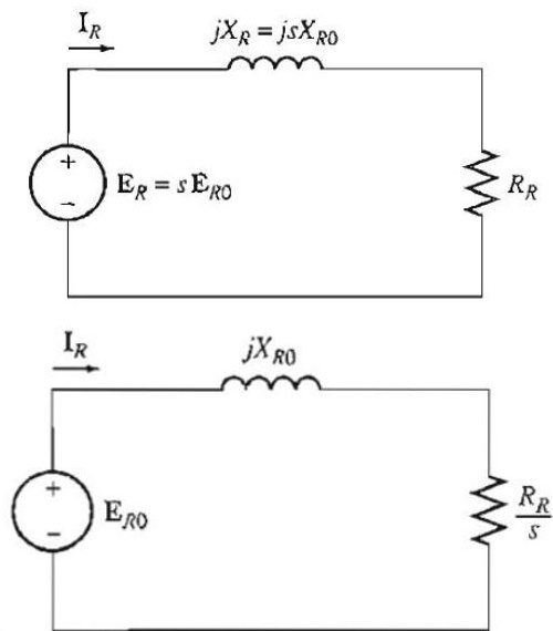
The resulting rotor equivalent circuit is shown in the figure.
The rotor Current flow can be found as
IR=RR+jXRER
IR=RR+jsXR0sER0
IR=RR/s+jXR0ER0
The equivalent rotor impedance from this point of view is
ZReq=RR/s+jXR0
and the rotor equivalent circuit using this convention is shown in figure
Equivalent Circuit of Induction Motor
To produce the final per-phase equivalent circuit for an induction motor, it is necessary to refer the rotor part of the model over to the stator side. If the effective turns ratio of an induction motor is aeff, then the transformed rotor voltage becomes
E1=ER′=aeffER0
the rotor current becomes
I2=aeffIR
And the rotor input impedance becomes
Z2=aeff2(sRR+jXR0)
Now if the following definitions are made:
R2=aeff2RR X2=aeff2XR0
then the final per-phase equivalent circuit of the induction motor is as shown in the following figure
Equivalent Circuit of Induction Motor