CT_Questions/CT_03.md
8.3 KB · commit d2f3b6e
Department of Electrical & Computer Engineering (ECE), RUET
2nd Year Even Semester (Session 2023-24)
Class Test (CT) Questions — CT-03
Course Code: ECE 2207
Course Title: Electrical Machines-I
Date: 26/08/2026
Time: 20 minutes
Total Marks: 20 (10 marks per question)
Question Paper Scan
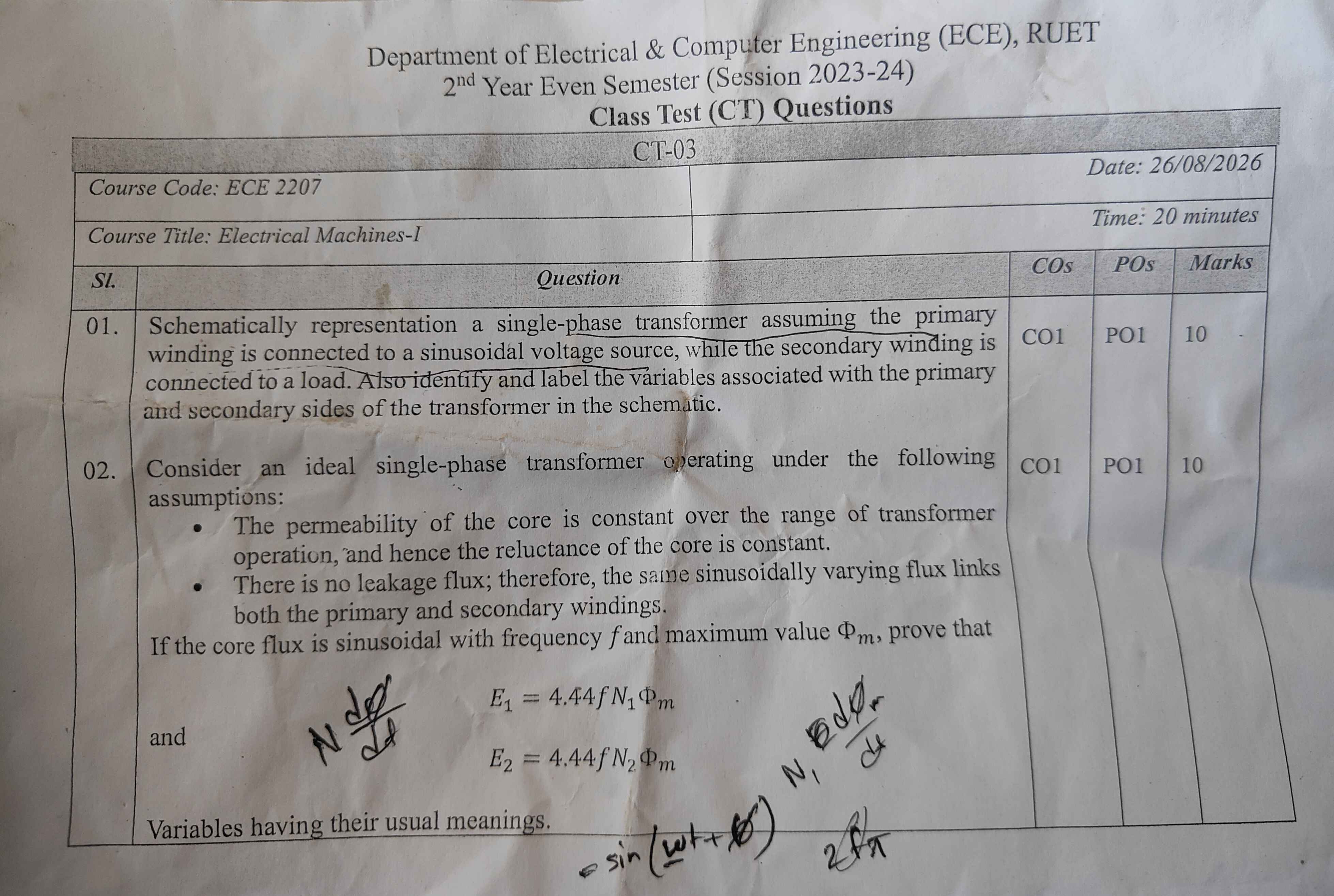
Question Paper Transcript
| Sl. | Question | COs | POs | Marks |
|---|---|---|---|---|
| 01. | Schematically representation a single-phase transformer assuming the primary winding is connected to a sinusoidal voltage source, while the secondary winding is connected to a load. Also identify and label the variables associated with the primary and secondary sides of the transformer in the schematic. | CO1 | PO1 | 10 |
| 02. | Consider an ideal single-phase transformer operating under the following assumptions: • The permeability of the core is constant over the range of transformer operation, and hence the reluctance of the core is constant. • There is no leakage flux; therefore, the same sinusoidally varying flux links both the primary and secondary windings. If the core flux is sinusoidal with frequency f and maximum value Φm, prove that E1=4.44fN1Φm and E2=4.44fN2Φm Variables having their usual meanings. | CO1 | PO1 | 10 |
(Note: "Schematically representation a single-phase transformer" appears verbatim from the original printed question sheet).
Comprehensive Solutions & Analysis
Question 01: Schematic Representation of a Single-Phase Transformer
Question: Schematically represent a single-phase transformer assuming the primary winding is connected to a sinusoidal voltage source, while the secondary winding is connected to a load. Also identify and label the variables associated with the primary and secondary sides of the transformer in the schematic. [Marks: 10, CO: 1, PO: 1]
1. Schematic Circuit Diagram
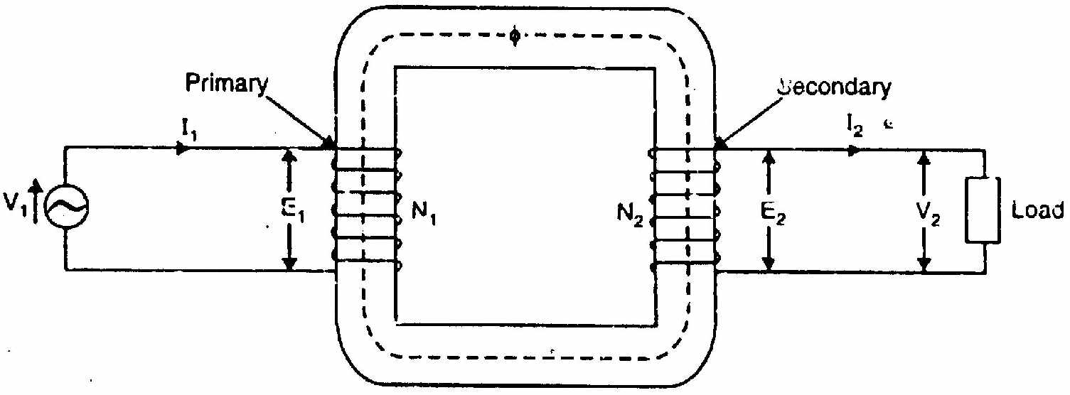
Core and Winding Schematic:
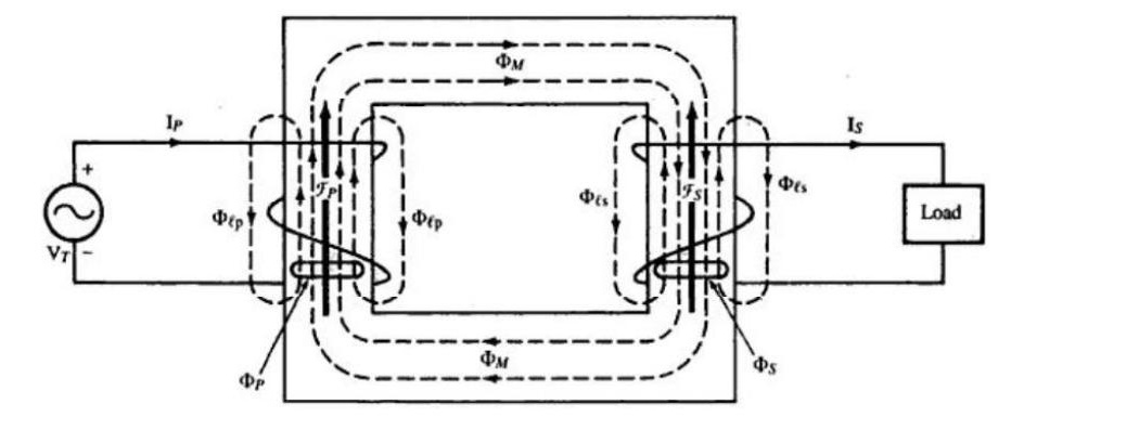
2. Identification and Labeling of Variables
Primary Side Variables:
- v1(t) or V1: Instantaneous and RMS primary applied terminal voltage (V).
- i1(t) or I1: Instantaneous and RMS primary current drawn from the sinusoidal AC source (A).
- N1: Number of turns on the primary winding.
- e1(t) or E1: Instantaneous and RMS counter electromotive force (self-induced EMF) in the primary winding (V).
- Polarity Dots (∙): Mark terminal polarity according to the right-hand rule.
Secondary Side Variables:
- N2: Number of turns on the secondary winding.
- e2(t) or E2: Instantaneous and RMS mutually induced electromotive force in the secondary winding (V).
- v2(t) or V2: Instantaneous and RMS secondary terminal voltage across the connected load (V).
- i2(t) or I2: Instantaneous and RMS secondary load current (A).
- ZL: Load impedance connected across the secondary terminals (Ω), where ZL=RL+jXL.
Core and Magnetic Variables:
- Φ(t): Instantaneous mutual magnetic flux linking both primary and secondary windings (Wb).
- Φm: Maximum (peak) value of mutual magnetic flux in the core (Wb).
- Bm: Maximum flux density in the core material (Bm=Φm/A, in Wb/m2 or Tesla).
- A: Effective cross-sectional area of the core limb (m2).
- f: Supply frequency (Hz), where ω=2πf (rad/s).
- K: Voltage transformation ratio (K=N1N2=E1E2).
Question 02: Derivation of the Transformer EMF Equation
Question: Under the assumptions of constant core permeability and zero leakage flux, prove that E1=4.44fN1Φm and E2=4.44fN2Φm. [Marks: 10, CO: 1, PO: 1]
1. Basis and Assumptions
- Constant permeability (μ=constant): The magnetic core does not saturate. Core reluctance R=μAl remains constant.
- Zero leakage flux: All magnetic flux remains confined to the iron core. Exactly the same flux Φ(t) links all N1 primary turns and all N2 secondary turns.
Let the sinusoidal core flux be: Φ(t)=Φmsin(ωt)=Φmsin(2πft)
Here:
- Φm = Maximum flux in the core (Wb)
- f = Frequency of the AC supply (Hz)
- ω=2πf = Angular frequency (rad/s)
2. Derivation for Primary Induced EMF (E1)
By Faraday's Law of Electromagnetic Induction, the instantaneous EMF induced in the primary winding is: e1(t)=−N1dtdΦ
Differentiate the flux expression: dtdΦ=dtd[Φmsin(ωt)]=ωΦmcos(ωt)
Substitute into the EMF equation: e1(t)=−N1ωΦmcos(ωt)
Using trigonometric identity −cos(θ)=sin(θ−90∘): e1(t)=N1ωΦmsin(ωt−2π)
This shows that the induced EMF lags the core flux by 90∘.
The maximum value (peak amplitude) of the primary induced EMF is: Em1=N1ωΦm=2πfN1Φm
For a pure sine wave, the Root-Mean-Square (RMS) value is: E1=2Em1=22πfN1Φm=2πfN1Φm
Substitute the numerical value of 2π: 2π≈1.4142×3.1416≈4.44288≈4.44
Therefore: E1=4.44fN1Φm
3. Derivation for Secondary Induced EMF (E2)
Because there is no leakage flux, the identical flux Φ(t) links all N2 turns of the secondary winding.
By Faraday's Law: e2(t)=−N2dtdΦ=−N2ωΦmcos(ωt)=N2ωΦmsin(ωt−2π)
The maximum secondary induced EMF is: Em2=N2ωΦm=2πfN2Φm
The RMS value of the secondary induced EMF is: E2=2Em2=22πfN2Φm=2πfN2Φm E2=4.44fN2Φm
(Both equations proved)
4. Alternative Method: Average EMF & Form Factor
In one quarter cycle of duration Δt=4T=4f1 seconds:
- Core flux increases from 0 to Φm.
- Change in flux ΔΦ=Φm−0=Φm Wb.
The average rate of change of flux is: ΔtΔΦ=1/(4f)Φm=4fΦm Wb/s
The average EMF induced per turn is: Average EMF per turn=4fΦm Volts
For a sine wave, the Form Factor Kf is: Kf=Average ValueRMS Value=1.11
Therefore: RMS value of EMF per turn=1.11×4fΦm=4.44fΦm Volts
Multiplying by the number of turns:
- For primary winding (N1 turns): E1=4.44fN1Φm
- For secondary winding (N2 turns): E2=4.44fN2Φm
Cross-References & Study Vault Links
- Classroom Board Notes: ClassNoteByRaidah/Class_13.md
- Faculty Lecture Slides: SlidesByMaam/L-06_ECE-2207.md
- Textbook Chapter: Books/B.L._Theraja/Ch-32_Transformer.md
- Semester Final Repeats: PrevYearQuestions/2024.md, PrevYearQuestions/2023.md, PrevYearQuestions/2021.md, PrevYearQuestions/2019.md (EMF equation is a primary repeat topic).