SlidesByMaam/L-06_ECE-2107.md
9.8 KB · commit d2f3b6e
Electrical Machines-I
ECE-2107
Induction Motor-SL5
Fariya Tabassum
Assistant Professor, Dept. of Electrical & Computer Engineering
Rajshahi University of Engineering & Technology, Rajshahi-6204
[Quranic Inscription]
“Truly, Allah is with those who fear him and those who are Muhsinun (good-doers)”.
[Sura An-Nahl]
Power Stages in an Induction Motor
The input electric power fed to the stator of the motor is converted into mechanical power at the shaft of the motor. The various losses during the energy conversion are:
- Fixed losses
- Stator iron loss (consisting of eddy and hysteresis loss)
- Friction and windage losss
The rotor iron loss is negligible because the frequency of rotor currents under normal running condition is small.
- Variable losses see article 7.4+ examle 7.2 of chapman, page 395
- Stator copper loss
- Rotor copper loss
Power Stages in an Induction Motor
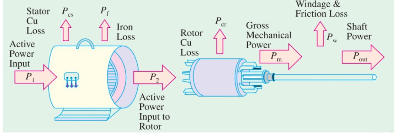
The following figure shows how electric power fed to the stator of an induction motor suffers losses and finally converted into mechanical power.
Power Stages in an Induction Motor
The following points may be noted from the previous diagam
(i) Stator input, Pi=Stator output+Stator losses
=Stator output+Stator iron loss+Stator Cu loss
(ii) Rotor input, Pr=Stator output
(iii) Mechanical power available, Pm=Pr−Rotor Cu loss
This mechanical power available is the gross rotor output and will produce a gross torque Tg.
(iv) Mechanical power at shaft, Pout=Pm−Friction and windage loss
Mechanical power available at the shaft produces a shaft torque Tsh.
Pm−Pout=Friction and windage loss
Torque Developed by an Induction Motor
The gross torque Tg can be represented by the gross power Pm as follows
Tg=ωPm=2πNPm
The shaft torque Tsh is due to the output power Pout which is less than Pm because of the friction and windage losses.
Tsh=ωPout=2πNPout
In the above expressions N is in r.p.s, if it is in r.p.m then the above expressions become
Tg=ω/60Pm=2πN60Pm=9.55NPm N−M
Tsh=ω/60Pout=2πN60Pout=9.55NPout N−M
Rotor Output
From the figure at slide no. 4,
Stator input, P1=Stator output+Stator losses
Obviously, rotor input, P2=Stator output
Rotor gross output, Pm=rotor input, P2−Rotor Cu loss
This rotor output is converted into mechanical energy and gives rise to gross torque, Tg. Out of this gross torque developed, some is lost due to windage and friction losses in the rotor and the rest appears as useful or shaft torque Tsh.
Tg=2πNPm(1)
If there were no copper losses in the rotor then rotor output will equal rotor input and the rotor will run at synchronous speed.
Tg=2πNsP2(2)
Rotor Output
Rotor gross output, Pm=Tgω=Tg×2πN
Rotor input, P2=Tgωs=Tg×2πNs(3)
The difference of these two equals rotor Cu loss
∴Rotor Cu loss=P2−Pm=Tg×2π(Ns−N)(4)
From (3) and (4)
Rotor inputRotor Cu loss=Ns(Ns−N)=s
Rotor Cu loss=s×Rotor input=sP2
Also rotor input=rotor Cu loss/s
Rotor gross output, Pm=input, P2−rotor Cu loss=P2−sP2=P2(1−s)
Rotor input, P2Rotor gross output, Pm=1−s=NsN
Rotor Output
Rotor efficiency=NsN=1−s
Hence the approximate efficiency of an induction motor is 1−s. Thus if the slip of an induction motor is 0.125, then its approximate efficiency is =1−0.125=0.875 or 87.5%.
Is some power P2 is delivered to a rotor then, a part sP2 is lost in the rotor itself as Cu loss (and appears as heat) and the remaining (1−s)P2 appears as gross mechanical power Pm (including friction and windage losses).
∴P2:Pm:I2Ror1:(1−s):s
Synchronous Watt
Tsw=2πNsRotor input, P2
Synchronous watt is that which, at the synchronous speed of machine under consideration would develop a power of 1 watt.
By defining a new unit of torque we can say that the rotor torque equals rotor input. The new unit is synchronous watt. When we say that a motor is developing a torque of 1,000 synchronous watts, we mean that the rotor input is 1,000 watt and that the torque is such that power developed would be 1,000 watts provided that the rotor was running synchronously and developing the same torque.
Starting of Induction Motor
Go for the article 35.9 of the book written by B. L. Theraza
Direct Switching or Line Starting of Induction Motor
With a current as great as 7 times the full-load current, the motor develops a starting torque which is only 1.96 times the full load value.
Go for the article 35.10 of the book written by B. L. Theraza
Starting Methods of Induction Motor
- Squirrel-cage Motors
- Primary resistors (or rheostat) or reactors
- Auto-transformer (or autostarter)
- Star-delta switches
In all of these methods the terminal voltage of the squirrel-cage motor is reduced during starting
- Slip-ring Motors
- Rotor rheostat
Starting of Squirrel-cage Motor
Primary resistors
Relation between starting and full load torque:
The ratio of starting torque to full load torque is x2 of that obtained with direct switching or across the line starting. This method is useful for the smooth starting of small machines only.
Go for the article 35.11 (a) of the book written by B. L. Theraza
Starting of Squirrel-cage Motor
Auto-transformer
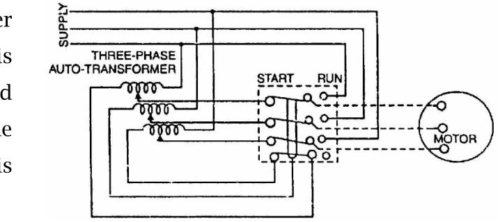
This method aims at connecting the induction motor to a reduced supply at starting and then connecting it to the full voltage as the motor picks up sufficient speed. Following Figure shows the circuit arrangement for autotransformer starting. The tapping on the autotransformer is so set that when it is in the circuit, 65% to 80% of line voltage is applied to the motor.
At the instant of starting, the change-over switch is thrown to “start” position. This puts the autotransformer in the circuit and thus reduced voltage is applied to the circuit. Consequently, starting current is limited to safe value.
Starting of Squirrel-cage Motor
When the motor attains about 80% of normal speed, the changeover switch is thrown to “run” position. This takes out the autotransformer from the circuit and puts the motor to full line voltage. Autotransformer starting has several advantages viz low power loss, low starting current and less radiated heat. For large machines (over 25 H.P.), this method of starting is often used. This method can be used for both star and delta connected motors.
Relation between starting and full load torque:
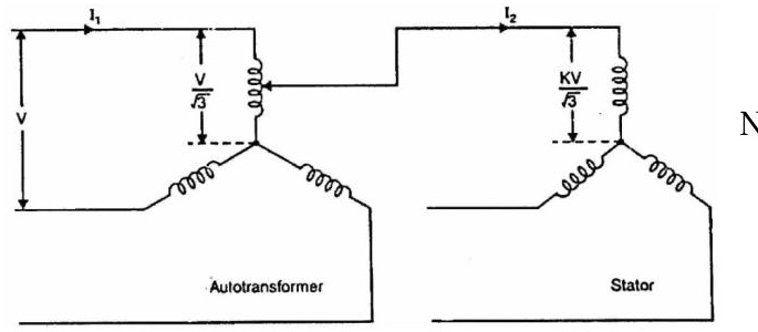
Let us consider a star-connected squirrel-cage induction motor. If V is the line voltage, then voltage across motor phase on direct switching is V/3 and starting current is Ist=Isc. In case of autotransformer, if a tapping of transformation ratio K (a fraction) is used, then phase voltage across motor is KV/3 and Ist=KIsc
Starting of Squirrel-cage Motor
Now
TfTst=(IfIst)2×sf=(IfKIsc)2×sf=K2(IfIsc)2×sf
∴TfTst=K2(IfIsc)2×sf
Practice example 34.10 of B. L. Theraza and also the related tutorial problem.
Starting of Squirrel-cage Motor
Star-delta starting
Relation between starting and full load torque:
TfTst=31(IfIsc)2×sf
The star-delta switch is equivalent to an autotransformer of ratio 1/3 or 58% approximately.
Go for the article 35.11 (c) of the book written by B. L. Theraza
Starting of Slip-ring Motor
Rotor rheostat
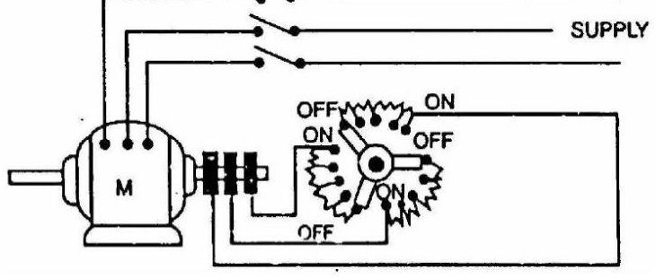
Slip-ring motors are invariably started by rotor resistance starting. In this method, a variable star-connected rheostat is connected in the rotor circuit through slip rings and full voltage is applied to the stator winding as shown in figure.
Starting of Slip-ring Motor
-
At starting, the handle of rheostat is set in the OFF position so that maximum resistance is placed in each phase of the rotor circuit. This reduces the starting current and at the same time starting torque is increased.
-
As the motor picks up speed, the handle of rheostat is gradually moved in clockwise direction and cuts out the external resistance in each phase of the rotor circuit. When the motor attains normal speed, the change-over switch is in the ON position and the whole external resistance is cut out from the rotor circuit.