CT_Questions/CT_04.md
8.6 KB · commit d2f3b6e
← CT-03 | 🏠 Index | CT Exam Answers →
Department of Electrical & Computer Engineering (ECE), RUET
2nd Year Even Semester (Session 2023-24)
Class Test (CT) Questions — CT-04
Course Code: ECE 2207
Course Title: Electrical Machines-I
Date: 09/09/2026
Time: 20 minutes
Total Marks: 20 (10 marks per question)
Question Paper Scan
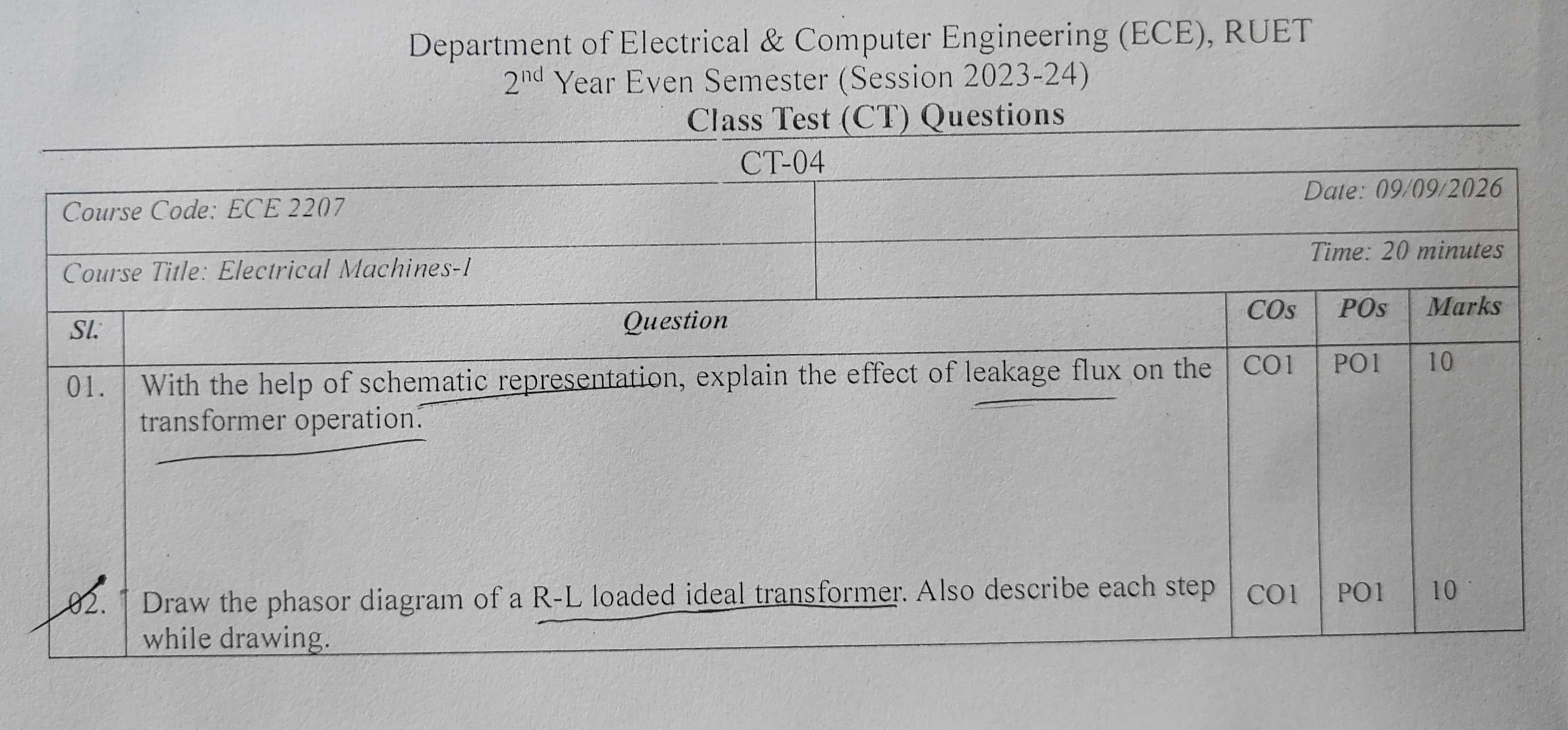
Question Paper Transcript
| Sl. | Question | COs | POs | Marks |
|---|---|---|---|---|
| 01. | With the help of schematic representation, explain the effect of leakage flux on the transformer operation. | CO1 | PO1 | 10 |
| 02. | Draw the phasor diagram of a R-L loaded ideal transformer. Also describe each step while drawing. | CO1 | PO1 | 10 |
Comprehensive Solutions & Analysis
Question 01: Leakage Flux and Its Effect on Transformer Operation
Question: With the help of schematic representation, explain the effect of leakage flux on the transformer operation. [Marks: 10, CO: 1, PO: 1]
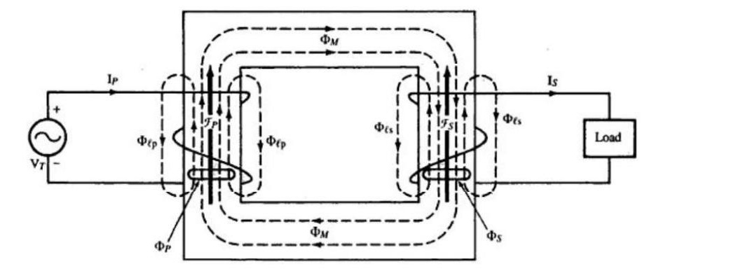
1. What is Leakage Flux?
In an actual transformer, not all magnetic flux stays within the iron core.
- Mutual Flux (Φm): The portion of flux that links both primary and secondary windings through the magnetic core. This flux transfers power between the windings.
- Primary Leakage Flux (Φl1): Flux set up by primary current I1 that links only the primary winding. It completes its path through the surrounding air and insulation.
- Secondary Leakage Flux (Φl2): Flux set up by secondary current I2 that links only the secondary winding. It also completes its path through air.
2. Schematic Representation of Leakage Flux
3. Physical Behavior of Leakage Flux
- The leakage paths lie mostly through air and insulating spaces.
- Air has constant magnetic permeability and does not saturate.
- Therefore, leakage flux is directly proportional to its respective winding current: Φl1∝I1andΦl2∝I2
- Each leakage flux is in phase with the current producing it.
4. Effects on Transformer Operation
1. Induction of Self-Leakage EMFs:
Because the leakage fluxes alternate with time, they induce self-EMFs in their own windings by Faraday's Law: el1=−N1dtdΦl1 el2=−N2dtdΦl2 Each self-induced leakage EMF lags its respective leakage flux (and current) by 90∘.
2. Representation as Leakage Reactances:
To supply current, the applied voltage must overcome this counter-EMF. The required opposing voltage leads the current by 90∘. This behaves like an inductive voltage drop across a series inductor: X1=2πfLl1=I1El1(Primary leakage reactance) X2=2πfLl2=I2El2(Secondary leakage reactance)
3. Internal Voltage Drops:
When the transformer is loaded, reactive voltage drops appear inside the windings:
- Primary internal reactive drop: jI1X1
- Secondary internal reactive drop: jI2X2
The terminal voltage equations become: V1=−E1+I1R1+jI1X1 V2=E2−I2R2−jI2X2
4. Impact on Voltage Regulation:
Under inductive (lagging power factor) loads, the leakage reactance drop subtracts directly from E2. This causes secondary terminal voltage V2 to decrease as load current increases. It worsens the voltage regulation of the transformer.
5. Fault Current Limitation:
Leakage reactance is not entirely harmful. During a secondary short circuit, the leakage reactances X1 and X2 provide the main impedance that limits fault current. This protects the transformer from mechanical destruction.
Question 02: Phasor Diagram of an R-L Loaded Ideal Transformer
Question: Draw the phasor diagram of a R-L loaded ideal transformer. Also describe each step while drawing. [Marks: 10, CO: 1, PO: 1]
1. Ideal Transformer Assumptions
- Winding resistances are zero (R1=R2=0).
- Leakage flux is zero (X1=X2=0).
- Core permeability is infinite (μ→∞). No magnetizing current is needed to set up core flux (Im=0).
- Core losses are zero (no hysteresis or eddy current losses, Ic=0).
- Therefore, no-load current is negligible (I0=0). The primary current balances the secondary load current: I1=I2′=N1N2I2=KI2
For an R-L load, secondary load current I2 lags secondary terminal voltage V2 by load impedance angle θ2: θ2=tan−1(RLXL)
2. Step-by-Step Construction Procedure
Follow these seven steps to draw the phasor diagram:
-
Step 1: Choose the Reference Phasor
Draw the mutual core flux phasor Φm horizontally along the positive X-axis. -
Step 2: Draw the Induced EMFs (E1 and E2)
By Faraday's Law, the induced EMFs lag the mutual flux Φm by 90∘. Draw E1 and E2 vertically downwards along the negative Y-axis. The relative lengths depend on the transformation ratio K=N2/N1. -
Step 3: Draw the Secondary Terminal Voltage (V2)
Because the transformer is ideal, there are no internal resistance or leakage reactance drops. Therefore, secondary terminal voltage equals secondary induced EMF: V2=E2 Draw V2 directly coinciding with E2, pointing vertically downward. -
Step 4: Draw the Secondary Load Current (I2)
The load has resistance and inductance (R-L). The load current I2 lags secondary terminal voltage V2 by phase angle θ2. Draw I2 clockwise from the downward vertical axis by angle θ2. -
Step 5: Draw the Primary Reflected Current (I1=I2′)
To keep core flux constant, primary ampere-turns must cancel secondary ampere-turns: N1I1+N2I2=0⟹I1=−N1N2I2 Draw I1 exactly 180∘ opposite to I2. Its magnitude is KI2. It points into the second quadrant. -
Step 6: Draw the Primary Applied Voltage (V1)
By Lenz's Law and Kirchhoff's Voltage Law, the applied primary voltage must balance the counter-EMF E1. Since there are no primary internal drops, V1=−E1. Draw V1 vertically upward along the positive Y-axis, exactly 180∘ out of phase with E1. -
Step 7: Mark the Primary Power Factor Angle (θ1)
Mark the angle between primary voltage V1 and primary current I1. Because V1 is opposite to V2 and I1 is opposite to I2, the primary phase angle equals the load phase angle: θ1=θ2 The primary side operates at the same lagging power factor (cosθ1=cosθ2) as the secondary load.
3. Complete Phasor Diagram
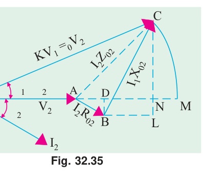
Vector Relationship Summary:
- Φm=Φm∠0∘ (Reference)
- E1=E1∠−90∘
- E2=V2=E2∠−90∘
- I2=I2∠(−90∘−θ2)
- V1=V1∠+90∘
- I1=I1∠(90∘−θ1) where θ1=θ2
Cross-References & Study Vault Links
- Classroom Board Notes on Leakage Reactance: ClassNoteByRaidah/Class_13.md
- Classroom Board Notes on Transformer Phasors: ClassNoteByRaidah/Class_14.md
- Faculty Lecture Slides: SlidesByMaam/L-06_ECE-2207.md, SlidesByMaam/L-07_ECE-2207.md
- Textbook Reference: Books/B.L._Theraja/Ch-32_Transformer.md
- Semester Final Repeats: PrevYearQuestions/2024.md (Question 2b asked for the R-L loaded transformer phasor diagram), PrevYearQuestions/2021.md, PrevYearQuestions/2018.md