boss_notes/T-06b_SC_Test.md
10.1 KB · commit d2f3b6e
← T-06a: OC Test | 🏠 Index | T-06c: Efficiency →
T-06b: Short-Circuit (SC) Test
Section: A | Priority: 🔴 MUST | Exam Frequency: 7/7 years Sources: Theraja Ch-32 (Art. 32.26–32.28), VK Mehta Ch-7 (Art. 7.20), Slides L-10 S18
Why This Topic Matters
The SC test always appears together with the OC test. ALL 7 papers include an OC/SC numerical. The SC test determines the series branch parameters (R01, X01, Z01) and the full-load copper loss. These parameters are then used to calculate voltage regulation and efficiency. In 2024, a new conceptual question appeared: "Why is the SC test done on the HV side?"
📝 Key Definitions
Short-Circuit (SC) Test (Impedance Test): "The purpose of this test is to determine (i) full-load copper loss and (ii) the equivalent resistance and leakage reactance of the transformer referred to the winding in which instruments are placed. In this test, the secondary (usually the low-voltage winding) is solidly short-circuited by a thick conductor. A low voltage is applied to the primary (usually HV winding) and is carefully adjusted till full-load currents are flowing in both primary and secondary." — VK Mehta, Art. 7.20
Copper loss (PCu): "The copper loss is the I2R loss in the windings due to resistance. At any fraction x of full load: PCu=x2PCu,FL. At half load, copper loss is only one-quarter of full-load copper loss." — From Theraja Art. 32.29
Test Setup and Procedure
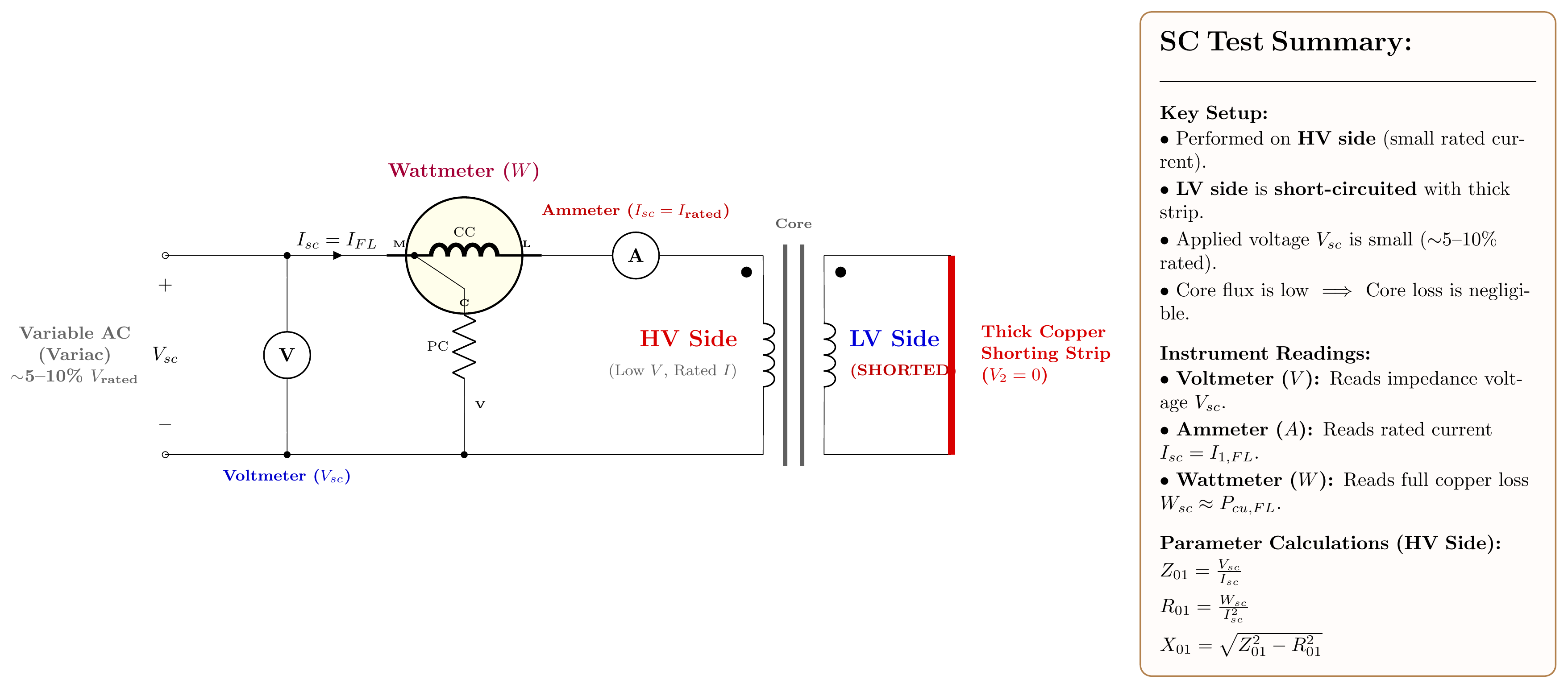
Connections (VK Mehta, Art. 7.20):
- Short-circuit the LV winding with a thick copper bar (very low resistance short).
- Apply a reduced voltage to the HV winding through a variac. Start from zero and increase gradually.
- Connect measuring instruments on the HV side:
- Voltmeter (Vsc) across the HV winding
- Ammeter (Isc) in series
- Wattmeter (Wsc)
- Increase voltage until Isc reaches the rated current of the HV winding. Stop. Record readings.
Why HV side?
- The rated current on the HV side is smaller (easier to measure).
- The required voltage to circulate rated current through the short is only 5–10% of rated voltage (safe and convenient).
- If done on the LV side, the required voltage would be even smaller and harder to measure accurately.
Readings taken: Vsc, Isc (= rated current), Wsc at rated current.
Parameter Extraction
Since the applied voltage is very low (5–10% of rated), the core flux is very small. Iron losses (which depend on flux) are negligible.
All power input = full-load copper loss:
PCu,FL=Wsc
This copper loss is at rated current. At any other load fraction x:
PCu=x2⋅PCu,FL
Series impedance (referred to the HV/test side):
Z01=IscVsc
R01=Isc2Wsc
X01=Z012−R012
To refer to the other side, divide by a2:
R02=R01/a2,X02=X01/a2,Z02=Z01/a2
Combined OC + SC Test: Complete Worked Example (PYQ 2024)
Problem: 20 kVA, 2000/400V transformer. OC test (HV open): 400V, 1.5A, 160W. SC test (LV short): 60V, rated I, 300W. Find: (i) equivalent circuit parameters referred to HV, (ii) efficiency at full-load 0.8 pf lag, (iii) voltage regulation.
Appeared: 2024 Q3(b) — 8 marks
Step 1: Identify Sides
- Turns ratio: a=2000/400=5
- OC test was done on LV (400V) side
- SC test was done on HV (2000V) side
Step 2: OC Test → Shunt Parameters
cosϕ0=V0I0W0=400×1.5160=0.2667
Iw=1.5×0.2667=0.400 A
Iμ=1.5×sin(cos−10.2667)=1.5×0.964=1.446 A
Referred to LV side:
Rc,LV=0.400400=1000Ω,Xm,LV=1.446400=276.6Ω
Referred to HV side (×a2=25):
Rc,HV=25000Ω,Xm,HV=6915Ω
Iron loss: PFe=W0=160 W
Step 3: SC Test → Series Parameters
Rated HV current: I1,rated=20000/2000=10 A
R01=Isc2Wsc=100300=3.0Ω
Z01=IscVsc=1060=6.0Ω
X01=6.02−3.02=27=5.196Ω
Copper loss: PCu,FL=Wsc=300 W
Step 4: Efficiency at Full-Load, 0.8 pf Lag
η=Scosϕ+PFe+PCu,FLScosϕ=16000+160+30020000×0.8=1646016000=97.2%
Step 5: Voltage Regulation at 0.8 pf Lag
VR%=V1I1(R01cosϕ+X01sinϕ)×100
=200010(3.0×0.8+5.196×0.6)×100=200010×5.518×100=2.76%
Exam Variants — The OC/SC Numerical Bank
| Year | Transformer | OC Data | SC Data | Asked For |
|---|---|---|---|---|
| 2017 Q6(c) | 500 kVA, 2300/208V | 208V, 85A, 1800W | 95V, 217.4A, 8200W | R02, parameters |
| 2018 Q2(b) | 10 kVA, 11kV/230V | 220V, 1.5A, 200W | 120V, rated I, 300W | η at FL/HL |
| 2019 Q2(c) | 10 kVA, 2200/220V | 220V, 1.5A, 153W | 115V, rated I, 224W | η at FL/HL |
| 2020 Q2(c) | Draw circuits | — | — | Circuit diagrams |
| 2021 Q2(c) | 20 kVA, 2400/240V | — | 72V, rated I, 275W | R01, X01, VR |
| 2023 Q2(b) | 2.2kV/220V | 220V, 0.8A, 80W | 12V, 10A, 40W | Eq. circuit to secondary |
| 2024 Q3(b) | 20 kVA, 2000/400V | 400V, 1.5A, 160W | 60V, rated I, 300W | Eq. circuit + η + VR |
🏆 Golden Questions (Past Exam Archive)
🎯 Q1: Given OC and SC test data, find equivalent circuit parameters, efficiency, and voltage regulation.
Appeared: 2017 Q6(c), 2018 Q2(b), 2019 Q2(c), 2021 Q2(c), 2023 Q2(b), 2024 Q3(b) — (4–8 marks)
Full Answer:
The procedure is always the same 5-step method. See the Complete Worked Example above for the full solution template (2024 data). For any other year's data, simply substitute the numbers into the same formulas:
Step 1: Identify which side each test was done on. OC test is usually on LV. SC test is usually on HV. Compute a=V1/V2.
Step 2 (OC test): PFe=W0. Then cosϕ0=W0/(V0I0). Then Iw=I0cosϕ0, Iμ=I0sinϕ0. Finally Rc=V0/Iw and Xm=V0/Iμ. To refer to other side: multiply by a2.
Step 3 (SC test): PCu,FL=Wsc. Then R01=Wsc/Isc2, Z01=Vsc/Isc, X01=Z012−R012.
Step 4 (Efficiency): η=xScosϕ/(xScosϕ+PFe+x2PCu,FL)
Step 5 (VR): VR%=I1(R01cosϕ±X01sinϕ)/V1×100
🎯 Q2: Why is the SC test performed on the HV side?
Appeared: 2024 Q2(b) — new pattern
Full Answer:
The SC test is performed on the HV side for three reasons:
(1) Lower current: The rated current on the HV side is smaller than on the LV side (since I∝1/V for the same kVA). Smaller current is easier and cheaper to supply from a variable AC source, and the ammeter can be lower-rated.
(2) Higher impedance, easier measurement: The HV winding has more turns, so its impedance (R01, X01) is larger. The short-circuit voltage Vsc needed to force rated current through the referred impedance is larger and more easily measured. If the test were done on the LV side, Vsc would be very small (perhaps only a few volts) and measurement accuracy would suffer.
(3) Safety: The voltage applied during the SC test is only 5–10% of rated HV voltage. This is a safe, low voltage. If the test were done on the LV side, even the small required voltage could be awkward to control precisely.
🎯 Q3: 2023 variant — OC: 220V, 0.8A, 80W; SC: 12V, 10A, 40W. Find equivalent circuit referred to secondary.
Appeared: 2023 Q2(b) — 6 marks
Full Answer:
Given: 2.2 kV/220V transformer.
OC test (done on LV = 220V side):
PFe=80 W
cosϕ0=80/(220×0.8)=0.4545
Iw=0.8×0.4545=0.3636 A, Iμ=0.8×sin(cos−10.4545)=0.8×0.8908=0.7127 A
Rc,LV=220/0.3636=605Ω, Xm,LV=220/0.7127=308.6Ω
(Already on the secondary/LV side since OC test was done there.)
SC test (done on HV = 2200V side):
a=2200/220=10
Isc=10 A. R01=40/100=0.4Ω, Z01=12/10=1.2Ω, X01=1.44−0.16=1.131Ω
Referred to secondary (divide by a2=100):
R02=0.4/100=0.004Ω, X02=1.131/100=0.01131Ω
⚡ Exam Tips & Common Mistakes
- SC test gives copper loss, not iron loss. Wsc=PCu,FL. At such low voltage, core flux is negligible, so iron loss ≈ 0.
- The ammeter must read rated current. If it reads something else, the copper loss must be scaled: PCu,FL=Wsc×(Irated/Isc)2.
- Check that R01<Z01. If R>Z, your calculation is wrong.
- Don't forget to identify which side each test was done on. OC → usually LV. SC → usually HV. Parameters are referred to the test side. To convert, use a2.
- Copper loss scales with x2. At half load: PCu=0.25×PCu,FL. At 75% load: PCu=0.5625×PCu,FL.
🔗 Related Topics
- T-06a: OC Test — The companion test for shunt parameters
- T-06c: Efficiency — Uses both PFe and PCu,FL
- T-05: Voltage Regulation — Uses R01 and X01
- T-04: Equivalent Circuit — The circuit model