boss_notes/T-04_Equivalent_Circuit.md
7.7 KB · commit d2f3b6e
← T-03b: Phasor Under Load | 🏠 Index | T-05: Voltage Regulation →
T-04: Equivalent Circuit
Section: A | Priority: 🟠 HIGH | Exam Frequency: 4/7 years Sources: Theraja Ch-32 (Art. 32.16–32.20), VK Mehta Ch-7 (Art. 7.12–7.15), Slides L-10
Why This Topic Matters
The equivalent circuit derivation appeared in 4/7 papers (2017, 2018, 2020, 2024). It ranges from "derive the equivalent circuit step by step" (4–5 marks) to using the circuit for numerical calculations. The OC/SC test (T-06a, T-06b) exists to find the parameters of this circuit. Master this topic and you have a framework for half of Section A.
📝 Key Definitions
Equivalent circuit: "Since the two windings of a transformer are coupled inductively, the transfer of energy from primary to secondary is by means of a mutual flux. To make analysis easier, we represent the transformer by an equivalent circuit in which all quantities are referred to one side, eliminating the magnetic coupling and replacing it with electrical quantities." — VK Mehta, Art. 7.12
Approximate equivalent circuit: "In a power transformer, the no-load current I0 is only about 2–5% of the full-load primary current. Therefore, the voltage drop across the primary impedance due to I0 is negligible. We can move the shunt branch to the input terminals. This enables combining the series impedances into single lumped parameters: R01=R1+R2′ and X01=X1+X2′." — Derived from Theraja Art. 32.18
Referring impedances: "To obtain a unified single electrical network and eliminate the ideal transformer block, all secondary impedances, voltages and currents are referred to the primary side. The transformation preserves power invariance: I22R2=(I2′)2R2′, giving R2′=a2R2 where a=N1/N2." — From Theraja Art. 32.17
Step-by-Step Circuit Development
Step 1: Ideal Transformer Model
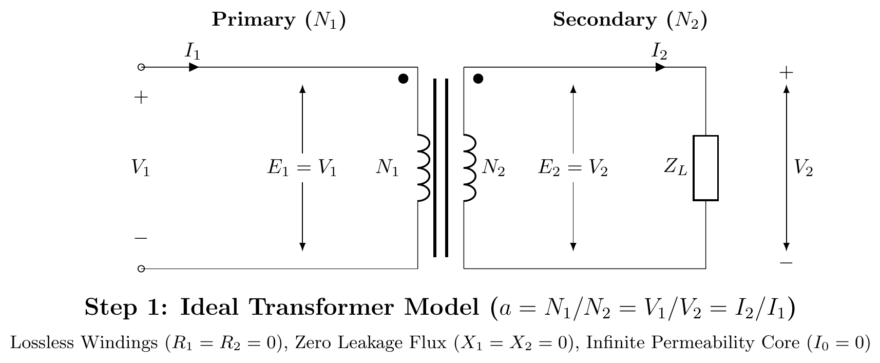
E2E1=N2N1=a,I2I1=a1
Step 2: Add Winding Resistances and Leakage Reactances
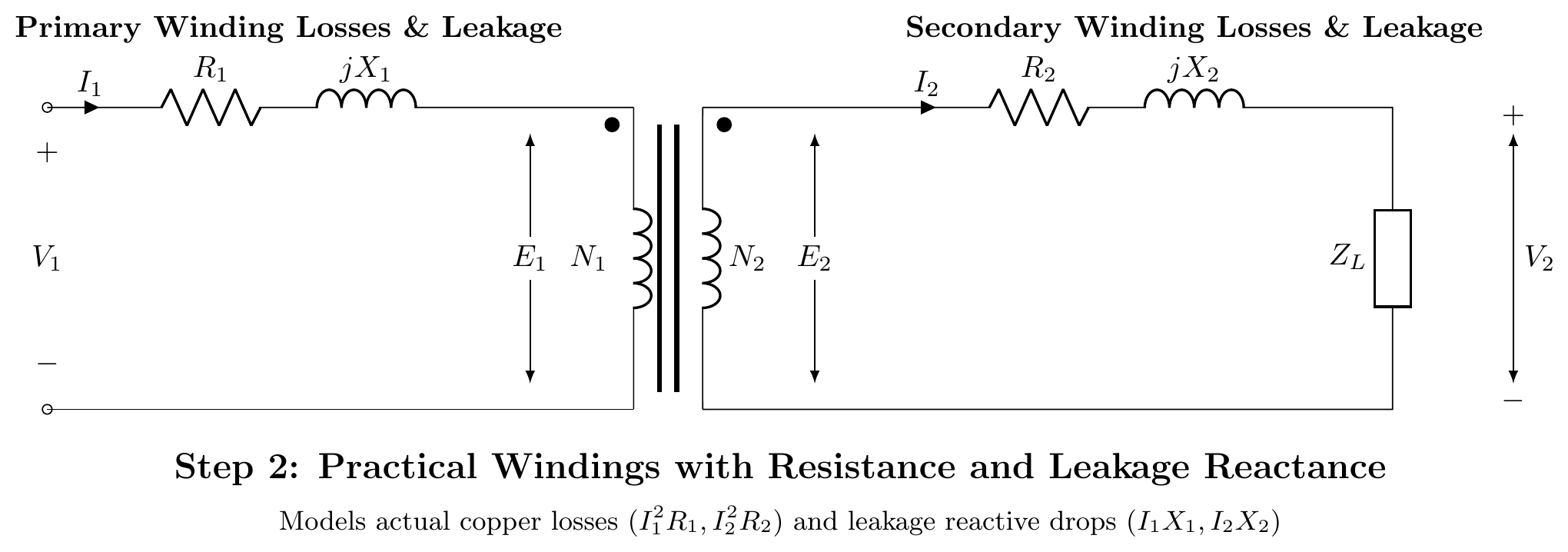
V1=E1+I1(R1+jX1),E2=V2+I2(R2+jX2)
Step 3: Add Excitation Shunt Branch
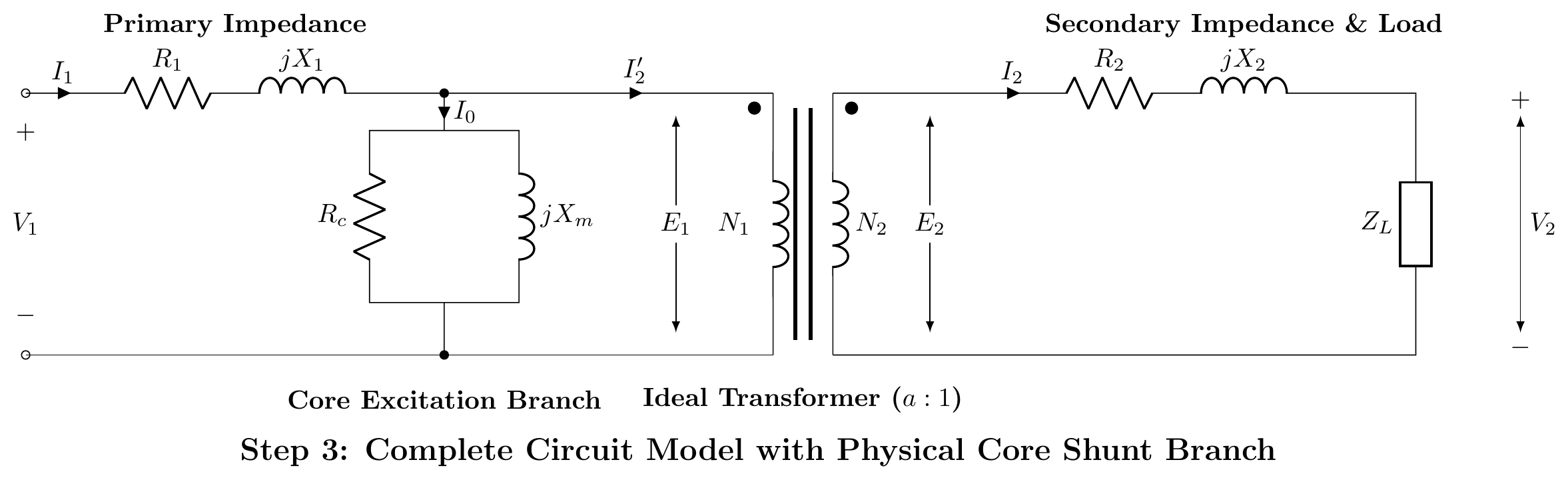
Rc=E1/Ic=E12/Pc (models iron losses). Xm=E1/Iμ (models magnetizing current).
I1=I0+I2′
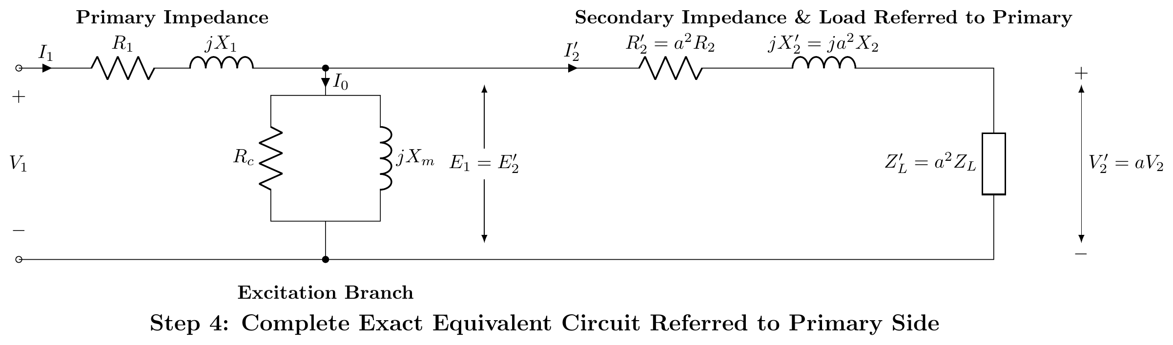
Step 4: Refer Secondary to Primary (Exact Equivalent Circuit)
| Quantity | Transformation | Referred Value |
|---|---|---|
| Voltage | Multiply by a | V2′=aV2, E2′=aE2=E1 |
| Current | Divide by a | I2′=I2/a |
| Resistance | Multiply by a2 | R2′=a2R2 |
| Reactance | Multiply by a2 | X2′=a2X2 |
| Impedance | Multiply by a2 | ZL′=a2ZL |
Step 5: Approximate Equivalent Circuit
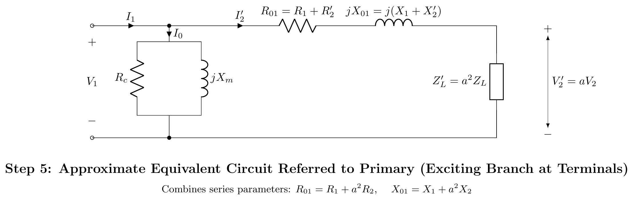
Move shunt branch to input terminals. Combine series impedances:
R01=R1+a2R2,X01=X1+a2X2
Step 6: Simplified Series Circuit (Neglecting I0)
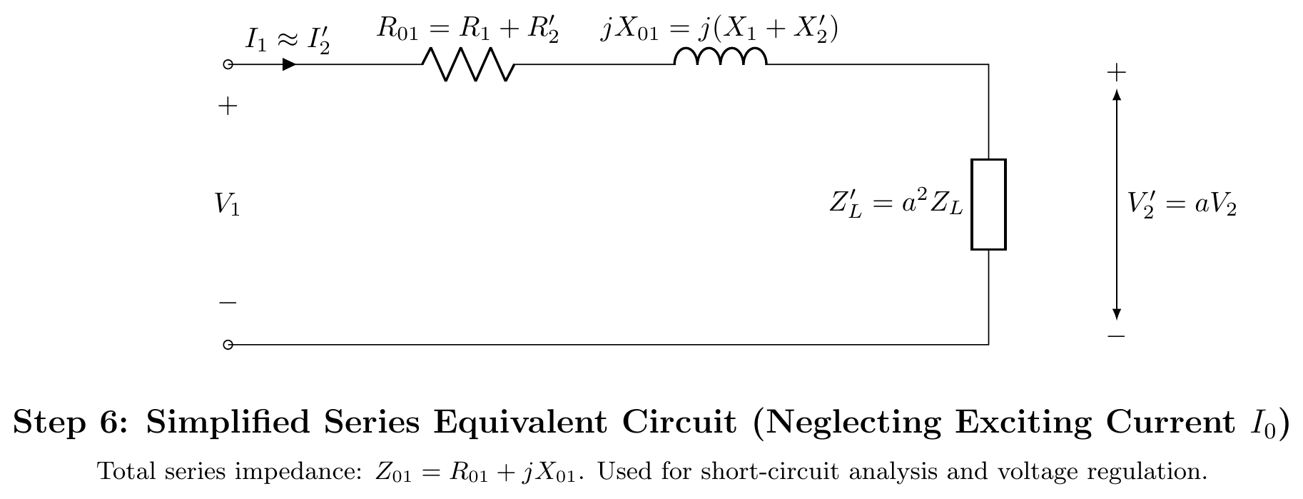
V1=V2′+I2′(R01+jX01)
🏆 Golden Questions (Past Exam Archive)
🎯 Q1: Derive the equivalent circuit of a single-phase two-winding transformer referred to the primary side (step by step).
Appeared: 2020 Q1(b) — 4 marks, 2020 Q3(c) — 5 marks, 2024 Q4(c) — 3 marks
Full Answer:
A practical two-winding transformer deviates from the ideal model due to four physical phenomena: (1) winding resistance (R1, R2) causing copper losses, (2) leakage flux causing leakage reactance (X1, X2), (3) finite core permeability requiring magnetizing current (Im) and iron losses requiring active current (Ic), and (4) turns ratio providing galvanic isolation.
Step 1 — Ideal Transformer Model: Start with zero losses, zero leakage, infinite permeability. E1/E2=N1/N2=a. V1=E1, V2=E2.
Step 2 — Add winding impedances: Model primary resistance R1 and leakage reactance X1 as series impedance on primary side. Similarly R2 and X2 on secondary. KVL: V1=E1+I1(R1+jX1) and E2=V2+I2(R2+jX2).
Step 3 — Add shunt excitation branch: Connect Rc∥jXm across the primary induced EMF E1. Rc=E12/Pc carries core-loss current Ic. Xm=E1/Im carries magnetizing current Im. By KCL: I1=I0+I2′.
Step 4 — Refer secondary to primary: To eliminate the ideal transformer block, convert all secondary quantities using the turns ratio a=N1/N2: V2′=aV2, I2′=I2/a, R2′=a2R2, X2′=a2X2, ZL′=a2ZL. The a2 rule for impedance comes from power invariance: I22R2=(I2′)2R2′.
This gives the Exact Equivalent Circuit referred to primary.
Step 5 — Approximate circuit: Since I0 is small (2–5% of rated), the drop I0(R1+jX1) is negligible. Move shunt branch to input terminals. Combine series: R01=R1+a2R2, X01=X1+a2X2.
Step 6 — Simplified series circuit: For full-load calculations, neglect I0 entirely. The transformer becomes: V1=V2′+I2′(R01+jX01).
🎯 Q2: Numerical — 200/400V step-up transformer. Given equivalent circuit parameters, find primary current and secondary voltage.
Appeared: 2017 Q8(c) — 5 marks
Full Answer:
Given: 200/400V step-up, Req=0.15Ω, Xeq=0.37Ω, Rc=600Ω, Xm=300Ω (all referred to LV/primary). Load: 10A at 0.8 pf lag on secondary.
Turns ratio: a=200/400=0.5
Refer load to primary: I2′=I2/a=10/0.5=20 A
I2′=20(0.8−j0.6)=16−j12 A
Primary voltage (taking V2′=200∠0° V as reference):
V1=V2′+I2′(R01+jX01)
(16−j12)(0.15+j0.37)=2.4+j5.92−j1.8+4.44=6.84+j4.12
V1=206.84+j4.12,∣V1∣=206.9 V
No-load current: Ic=206.9/600=0.345 A, Iμ=206.9/300=0.690 A
I0=0.345−j0.690 A
Total primary current: I1=(16.345−j12.69) A
∣I1∣=16.3452+12.692=20.7 A
Secondary terminal voltage: V2=V2′/a=200/0.5=400 V
⚡ Exam Tips & Common Mistakes
- Remember the a2 rule for impedances. Voltage scales by a, current by 1/a, impedance by a2.
- Draw all 5 (or 6) steps when asked for "step-by-step." Each step carries marks.
- The shunt branch goes across E1 in the exact circuit, across V1 in the approximate circuit.
- OC test → shunt branch (Rc, Xm). SC test → series branch (R01, X01).
🔗 Related Topics
- T-03b: Phasor Under Load — Phasor analysis of this circuit
- T-05: Voltage Regulation — Uses Step 6 circuit
- T-06a: OC Test — Finds Rc, Xm
- T-06b: SC Test — Finds R01, X01
← T-03b: Phasor Under Load | 🏠 Index | T-05: Voltage Regulation →