boss_notes/T-03a_No-Load_Operation.md
10.0 KB · commit d2f3b6e
← T-02: Construction | 🏠 Index | T-03b: Phasor Diagrams Under Load →
T-03a: No-Load Operation
Section: A | Priority: 🟠 HIGH | Exam Frequency: 3/7 years Sources: Theraja Ch-32 (Art. 32.6–32.9), VK Mehta Ch-7 (Art. 7.4–7.6), Slides L-09 S04–S08
Why This Topic Matters
No-load operation is tested in 3/7 papers (2019, 2020, 2024). It appears as "explain no-load operation with phasor diagram" (3–6 marks) or as a numerical where you decompose I0 into its components. Understanding no-load current is also the foundation for the OC test (T-06a) and the shunt branch of the equivalent circuit (T-04). A near-identical numerical (220V/110V, 0.5A, 30W) was repeated in 2020 and 2024.
📝 Key Definitions
No-load current (I0): "When the primary of a transformer is connected to the supply and the secondary is open, the transformer is on no-load. The small current I0 taken by the primary under no-load conditions is called no-load current." — VK Mehta, Art. 7.6. It is typically 2–10% of rated current.
Magnetizing current (Iμ or Im): "The component Iμ of I0 which establishes the alternating flux Φm in the core is called the magnetizing current. It is in phase with the flux Φm and lags V1 by 90°." — VK Mehta, Art. 7.6
Core-loss current (Iw or Ic): "The component Iw of I0 which supplies the iron losses (hysteresis + eddy current) is called the active or working or iron-loss component. It is in phase with V1." — VK Mehta, Art. 7.6
What Happens at No-Load
When you apply V1 to the primary and leave the secondary open (I2=0):
- A small no-load current I0 flows in the primary.
- This current does two jobs:
- Magnetic job: The magnetizing component Iμ sets up the alternating core flux Φm.
- Thermal job: The core-loss component Iw supplies power for hysteresis and eddy current losses.
- The flux Φm induces EMFs in both windings: E1=4.44fN1Φm and E2=4.44fN2Φm.
- Since the secondary is open, no current flows there. V2=E2.
No-Load Current Components
The no-load current I0 splits into two perpendicular components:
I0=Iw2+Iμ2
where:
- Iw=I0cosϕ0 (active component, in phase with V1)
- Iμ=I0sinϕ0 (reactive component, 90° lagging from V1)
The no-load power factor is very low (0.1–0.3) because Iμ≫Iw. The magnetizing current dominates.
No-load power input:
W0=V1I0cosϕ0=V1Iw
This power equals the iron loss (core loss) because copper loss at no-load is negligible (I0 is tiny, so I02R1≈0).
cosϕ0=V1I0W0
No-Load Phasor Diagram
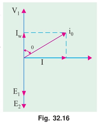
Step-by-step construction:
- Draw Φm as the reference (horizontal, pointing right).
- E1 and E2 lag Φm by 90° (pointing downward). The induced EMF is maximum when flux passes through zero.
- V1=−E1 (pointing upward). The applied voltage must balance the back-EMF.
- Iw is in phase with V1 (pointing upward). It supplies real power for core losses.
- Iμ lags V1 by 90°. It points in the same direction as Φm (horizontal right). This makes sense: the magnetizing current creates the flux, so they are in phase.
- I0=Iw+Iμ (phasor sum). The angle between V1 and I0 is ϕ0.
- Since secondary is open: V2=E2 (no drops).
Why Primary Current Increases with Load
When you connect a load and secondary current I2 flows:
- I2 through N2 turns creates a demagnetizing MMF = N2I2.
- This tends to reduce the core flux.
- But V1 is fixed by the supply. Since V1≈E1=4.44fN1Φm, the flux must stay constant.
- The primary draws additional current I2′ to cancel the secondary MMF:
N1I1=N1I0+N2I2
I1=I0+N1N2I2=I0+I2′
"The increased primary current brings in more energy from the supply to match the energy delivered to the load. The transformer does not generate energy: it regulates primary current to always match the secondary load." — From explanation notes
🏆 Golden Questions (Past Exam Archive)
🎯 Q1: Explain the no-load operation of a 1-phase transformer with a neat phasor diagram.
Appeared: 2020 Q1(c) — 3 marks, 2024 Q1(b) — 6 marks
Full Answer:
When a transformer primary is connected to AC supply with secondary open-circuited, a small no-load current I0 flows (2–10% of rated current). This current has two components:
1. Magnetizing current (Iμ): This component establishes the alternating mutual flux Φm in the core. It is purely reactive and lags the applied voltage V1 by 90°. It is in phase with the flux Φm. It does no real work — it simply oscillates the magnetic field back and forth.
2. Core-loss (active) current (Iw): The core heats up due to hysteresis and eddy current losses. These losses require real power input. Iw is in phase with V1 and supplies this power.
The total no-load current is the phasor sum:
I0=Iw2+Iμ2
The no-load power factor is very low (cosϕ0=0.1 to 0.3) because Iμ≫Iw.
No-load power input: W0=V1I0cosϕ0=V1Iw=Piron (copper loss is negligible)
Phasor Diagram Construction:
- Draw Φm horizontal as reference.
- E1, E2 lag Φm by 90° (downward). By Faraday's law: e=−NdΦ/dt, so EMF is maximum when flux passes through zero.
- V1=−E1 (upward). Applied voltage balances the back-EMF.
- Iw is in phase with V1 (upward).
- Iμ is in phase with Φm (horizontal right). Lags V1 by 90°.
- I0=Iw+Iμ at angle ϕ0 from V1.
- Since secondary is open: V2=E2 (no load drops).
🎯 Q2: No-load test data: 220V/110V, 0.5 A, 30 W. Find magnetizing and core-loss components.
Appeared: 2020 Q2(d), 2024 Q3(c) — identical data in both years
Full Answer:
Given: V1=220 V, V2=110 V, I0=0.5 A, W0=30 W.
No-load power factor:
cosϕ0=V1I0W0=220×0.530=11030=0.2727
ϕ0=cos−1(0.2727)=74.17°
Core-loss (active) current:
Iw=I0cosϕ0=0.5×0.2727=0.136 A
Magnetizing (reactive) current:
Iμ=I0sinϕ0=0.5×sin(74.17°)=0.5×0.9621=0.481 A
Iron loss: PFe=W0=30 W (copper loss at no-load is negligible since I0 is very small)
Check: I0=0.1362+0.4812=0.0185+0.2314=0.2499=0.5 A ✓
Note that Iμ≫Iw. The no-load current is mostly magnetizing.
🎯 Q3: Why does primary current increase as secondary load increases?
Appeared: 2019 Q1(c) — 4 marks
Full Answer:
An ideal transformer maintains the core flux Φm at a constant value set by the supply voltage: Φm≈V1/(4.44fN1). This flux requires a certain MMF to sustain it.
At no-load, the primary alone provides all the required MMF: N1I0=const.
When a load draws secondary current I2, the secondary winding (with N2 turns) creates a demagnetizing MMF =N2I2. This tends to reduce the core flux.
But V1 is fixed by the supply. Since V1≈E1=4.44fN1Φm, the flux cannot change (it is locked to the supply voltage). Therefore, the primary current must increase to cancel the secondary demagnetization:
N1I1−N2I2=N1I0≈const
N1I1=N1I0+N2I2
I1=I0+N1N2I2=I0+I2′
As I2 increases (more load), I1 increases proportionally. The increased primary current brings in more energy from the supply to match the energy delivered to the load. The transformer does not generate energy; it acts as an automatic current regulator that adjusts I1 to always balance the secondary MMF.
Exam Variants
| Year | Question | Data Given | Key Answer |
|---|---|---|---|
| 2020 Q2(d) | Find Iμ, Iw | 220V/110V, I0=0.5 A, W0=30 W | Iw=0.136 A, Iμ=0.481 A |
| 2024 Q3(c) | Same problem | Identical data | Same answers |
| 2019 Q1(c) | Why does I1 increase with load? | Conceptual | MMF balance argument |
| 2020 Q1(c) | Explain no-load with sketch | Conceptual | Phasor diagram + components |
| 2024 Q1(b) | No-load with phasor diagram | Conceptual, 6 marks | Full phasor construction |
⚡ Exam Tips & Common Mistakes
- Iμ is the bigger component. Students often swap Iw and Iμ. Remember: most of the no-load current goes into creating flux (Iμ), not into losses (Iw). The no-load pf is low (0.1–0.3).
- No-load power = iron loss only. Copper loss at no-load is negligible because I0 is tiny. So W0=Piron.
- The phasor diagram uses Φm as reference, not V1. Start with flux horizontal. Everything else follows from there.
- The 220V/110V, 0.5A, 30W numerical is a guaranteed repeat. Memorize the answers.
🔗 Related Topics
- T-01: Fundamentals — EMF equation that determines the flux
- T-03b: Phasor Under Load — Adding load to the no-load diagram
- T-04: Equivalent Circuit — R0 and X0 come from no-load data
- T-06a: OC Test — The OC test IS the no-load test
← T-02: Construction | 🏠 Index | T-03b: Phasor Diagrams Under Load →