boss_notes/T-01_Transformer_Fundamentals.md
13.1 KB · commit d2f3b6e
← T-00: Core Fundamentals | 🏠 Index | T-02: Construction →
T-01: Transformer Fundamentals & EMF Equation
Section: A | Priority: 🟠 HIGH | Exam Frequency: 4/7 years Sources: Theraja Ch-32 (Art. 32.1–32.5), VK Mehta Ch-7 (Art. 7.1–7.3), Slides L-08
Why This Topic Matters
The EMF equation E=4.44fNΦm appeared in 4 out of 7 papers (2019, 2021, 2023, 2024). It is the foundation for every transformer calculation. Questions range from "derive the EMF equation" (3–6 marks) to numericals asking you to find turns, flux, or voltages. If you know this derivation cold, you also understand the working principle of every AC machine.
📝 Key Definitions
Transformer: "A transformer is a static (or stationary) piece of apparatus by means of which electric power in one circuit is transformed into electric power of the same frequency in another circuit. It can raise or lower the voltage in a circuit but with a corresponding decrease or increase in current. The physical basis of a transformer is mutual induction between two circuits linked by a common magnetic flux." — Theraja, Art. 32.1
Voltage Transformation Ratio (K): "The constant K=E2/E1=N2/N1 is known as voltage transformation ratio. If N2>N1 i.e. K>1, the transformer is called a step-up transformer. If N2<N1 i.e. K<1, it is called a step-down transformer." — Theraja, Art. 32.7
Ideal Transformer: "An ideal transformer is one that has (1) no winding resistance, so there is no ohmic voltage drop and no copper loss; (2) no magnetic leakage flux, so all flux links both windings; (3) no core/iron loss, meaning the core has infinite permeability and zero hysteresis and eddy-current losses. Although an ideal transformer cannot be physically realized, its study provides a very powerful tool in the analysis of a practical transformer." — VK Mehta, Art. 7.2
How a Transformer Works
A transformer has two windings (primary and secondary) wound on a common iron core. There is no electrical connection between them. Energy transfers through the magnetic field.
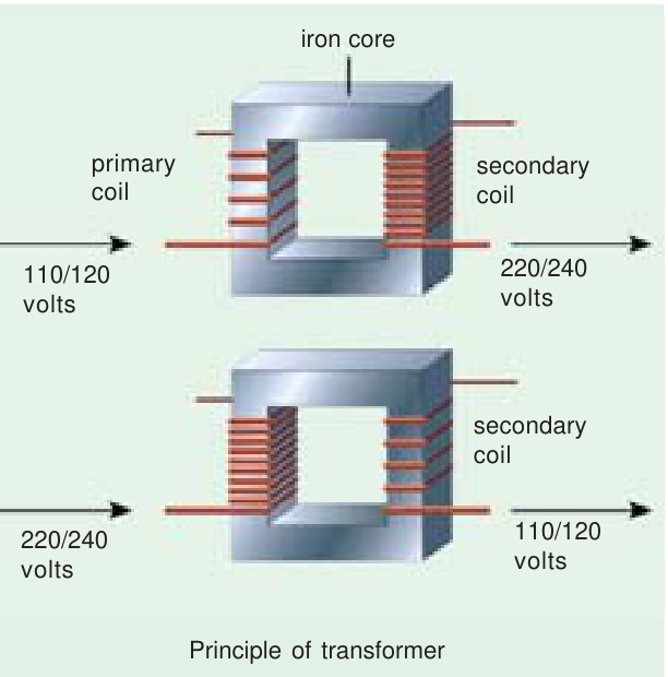
Step 1: Apply AC voltage to the primary. When you connect the primary (N1 turns) to an AC supply V1, a small current flows. This current creates an alternating magnetic flux Φ in the iron core.
Step 2: Flux induces EMF in both windings. By Faraday's law, the changing flux induces an EMF in every coil it passes through:
e1=−N1dtdΦ,e2=−N2dtdΦ
The ratio of EMFs equals the turns ratio:
E2E1=N2N1
Step 3: Load draws current. When a load connects to the secondary, current I2 flows. This current tries to reduce the core flux (Lenz's law). But the supply voltage forces the flux to stay constant. So the primary draws more current I1 to compensate.
Step 4: Power is conserved. For an ideal transformer: V1I1=V2I2. The transformer changes the voltage-current ratio while keeping power constant.
The following points (from VK Mehta, Art. 7.1) should be noted:
- Transformer action is based on mutual induction between two circuits linked by a common magnetic flux.
- The frequency of induced EMF is the same as that of the applied voltage.
- The two windings are not electrically connected; they are magnetically coupled.
- Electrical power is transferred from primary to secondary with negligible loss.
Ideal Transformer Properties
An ideal transformer assumes (Theraja, Art. 32.5):
- Zero winding resistance (R1=R2=0). No I2R losses and no ohmic voltage drop.
- Zero leakage flux. All flux produced by primary links the secondary. No leakage reactance.
- Zero core losses. Core has infinite permeability. No hysteresis or eddy current losses. Magnetizing current Iμ≈0.
"It may be noted that it is impossible to realize such a transformer in practice, yet for convenience, we start with such a transformer and step by step approach an actual transformer." — Theraja
Key relationships for an ideal transformer:
V2V1=N2N1=I1I2=a
where a=N1/N2 is the turns ratio.
EMF Equation Derivation
This is the most important derivation in the transformer chapter. Two methods exist. Know both.
Method 1: Calculus Method (Primary)
Step 1: Write the flux waveform. The core flux is sinusoidal:
Φ(t)=Φmsin(2πft)
where Φm is the peak flux in webers and f is frequency in Hz.
Step 2: Apply Faraday's law for a winding of N1 turns:
e1(t)=−N1dtdΦ=−N1⋅2πfΦmcos(2πft)
Since −cosθ=sin(θ−90°):
e1(t)=N1⋅2πfΦmsin(2πft−90°)
This tells us the EMF lags the flux by 90°. When flux is at its peak, the rate of change is zero, so EMF is zero at that instant.
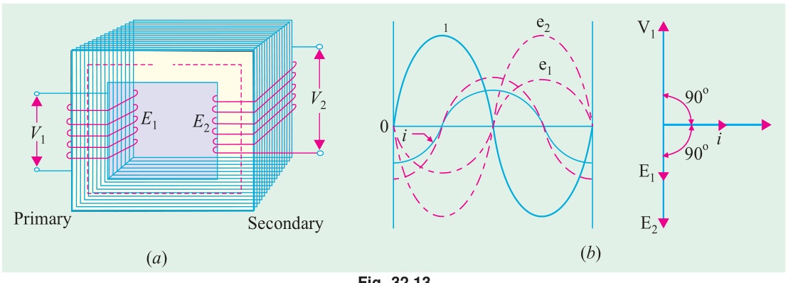
Step 3: Find the peak EMF:
Em1=2πfN1Φm
Step 4: Convert to RMS. For a sine wave, RMS = peak/2:
E1=22πfN1Φm=2πfN1Φm
Step 5: Compute the constant:
2π=1.4142×3.1416=4.443≈4.44
E1=4.44fN1Φm
The same flux links the secondary (N2 turns):
E2=4.44fN2Φm
Method 2: Form Factor Method (Theraja, Art. 32.6)
"Flux increases from its zero value to maximum value Φm in one quarter of the cycle i.e. in 1/4f second." — Theraja
Average rate of change of flux=1/(4f)Φm=4fΦm Wb/s (= volt/turn)
For a sine wave, the form factor (ratio of RMS to average of full-wave rectified value):
Kf=Average valueRMS value=1.11
RMS EMF per turn =1.11×4fΦm=4.44fΦm
Multiply by turns: E1=4.44fN1Φm ✓
Transformation Ratio
Dividing the two EMF equations (Theraja, Art. 32.7):
E1E2=N1N2=K
For an ideal transformer (V1≈E1, V2≈E2):
V1V2=N1N2=K
From power conservation (V1I1=V2I2):
I2I1=V1V2=K
"Hence, currents are in the inverse ratio of the (voltage) transformation ratio." — Theraja
| Transformer Type | Condition | Effect |
|---|---|---|
| Step-up | K>1 (N2>N1) | Voltage increases, current decreases |
| Step-down | K<1 (N2<N1) | Voltage decreases, current increases |
🏆 Golden Questions (Past Exam Archive)
🎯 Q1: Derive the transformer EMF equation under assumptions of constant permeability and no leakage flux.
Appeared: 2019 Q1(b), 2021 Q1(b), 2023 Q1(b), 2024 Q4(a) — (3–6 marks)
Full Answer:
Let N1 = primary turns, N2 = secondary turns, Φm = peak flux (Wb), f = frequency (Hz).
The core flux is sinusoidal: Φ(t)=Φmsin(ωt) where ω=2πf.
By Faraday's law, instantaneous EMF induced in primary:
e1=−N1dtdΦ=−N1ωΦmcos(ωt)=N1ωΦmsin(ωt−90°)
Peak EMF: Em1=2πfN1Φm
RMS EMF: E1=Em1/2=2πfN1Φm/2
E1=4.44fN1Φm
Similarly: E2=4.44fN2Φm
The EMF per turn is the same in both windings: E1/N1=E2/N2=4.44fΦm
Also: E1/E2=N1/N2=K (voltage transformation ratio).
🎯 Q2: What are the characteristics of an ideal transformer?
Appeared: 2021 Q1(a), 2024 Q1(a) — (3–6 marks)
Full Answer:
An ideal transformer is one which has no losses (Theraja, Art. 32.5). It has:
- No winding resistance (R1=R2=0): No ohmic voltage drop (IR=0) and no copper loss (I2R=0).
- No magnetic leakage flux: All the flux produced by the primary links the secondary winding completely. There is no leakage flux. Hence leakage reactances are zero (X1=X2=0).
- No core (iron) losses: The core has infinite permeability, so the magnetizing current needed to establish flux is zero (Iμ=0). Hysteresis and eddy current losses are zero.
For such a transformer:
- Input VA = Output VA: V1I1=V2I2
- Voltage ratio = Turns ratio: V1/V2=N1/N2=a
- Current ratio = Inverse turns ratio: I1/I2=N2/N1=1/a
- Efficiency = 100%
"It is impossible to realize such a transformer in practice, yet for convenience we start with such a transformer and step by step approach an actual transformer." — Theraja
🎯 Q3: Show the schematic of a 1-φ transformer. Identify and label all variables on both sides.
Appeared: 2023 Q1(a), 2024 Q1(a) — (6 marks)
Full Answer:
Draw a transformer with a laminated iron core and two windings:
Primary side (left):
- Applied voltage V1 from AC supply
- Primary current I1 entering the dot terminal
- N1 turns on the primary winding
- Self-induced EMF E1 (opposing V1)
Core (center):
- Alternating mutual flux Φ(t)=Φmsinωt flowing through the laminated iron core
Secondary side (right):
- N2 turns on the secondary winding
- Mutually induced EMF E2
- Secondary current I2 (flows when load ZL is connected)
- Terminal voltage V2 across the load
Key relationships to state:
- E1/E2=N1/N2 (EMF ratio = turns ratio)
- V1I1=V2I2 (power conservation for ideal case)
- K=N2/N1 (transformation ratio)
- If K>1: step-up; if K<1: step-down
🎯 Q4: 25 kVA transformer, 500/50 turns, 3000V/50Hz. Find full-load currents, secondary EMF, max flux.
Appeared: 2021 Q1(c) — 4 marks
Full Answer:
Given: S=25 kVA, N1=500, N2=50, V1=3000 V, f=50 Hz.
Turns ratio: a=N1/N2=500/50=10
Secondary EMF: E2=V1/a=3000/10=300 V
Full-load currents:
I1=V1S=300025000=8.33 A
I2=V2S=30025000=83.3 A
Maximum flux (from EMF equation, E1≈V1):
Φm=4.44fN1E1=4.44×50×5003000=1110003000=27.03 mWb
Check: E2=4.44×50×50×0.02703=300 V ✓
🎯 Q5: 50 Hz, 6.6 kV/400V transformer. Core cross-section = 25 cm², max flux density = 1.2 T. Find number of turns on each side.
Appeared: 2024 Q4(b) — 3 marks
Full Answer:
Given: f=50 Hz, V1=6600 V, V2=400 V, A=25 cm² =25×10−4 m², Bm=1.2 T.
Maximum flux:
Φm=Bm×A=1.2×25×10−4=3×10⁻³ Wb
Primary turns (from EMF equation):
N1=4.44fΦmE1=4.44×50×3×10−36600=0.6666600=9910 turns
Secondary turns:
N2=4.44fΦmE2=0.666400=600 turns
Check: N1/N2=9910/600=16.5=V1/V2=6600/400=16.5 ✓
Exam Variants
| Year | Question | Data Given | Key Answer |
|---|---|---|---|
| 2021 Q1(c) | Find currents, EMF, flux | 25 kVA, 500/50 turns, 3000V/50Hz | Φm=27.03 mWb |
| 2024 Q4(b) | Find number of turns | 50Hz, 6.6kV/400V, A=25 cm², Bm=1.2 T | N1=9910, N2=600 |
| 2019 Q1(b) | Derive EMF equation | — | E=4.44fNΦm |
| 2023 Q1(b) | Derive EMF equation | — | Same derivation |
⚡ Exam Tips & Common Mistakes
- Don't confuse K and a. K=N2/N1 (transformation ratio, Theraja convention). a=N1/N2 (turns ratio). They are reciprocals. Use whichever the question defines. If not defined, state your convention.
- EMF equation uses peak flux Φm, not RMS. A common error is plugging in RMS flux values.
- Frequency must be in Hz, not rad/s. The 4.44 constant already includes 2π/2.
- Show every step in the derivation. Don't jump from Faraday's law to the final answer. The intermediate steps (−cosθ to sin(θ−90°), peak to RMS conversion) carry marks.
- Cross-check with turns ratio. After finding N1 and N2, verify N1/N2≈V1/V2.
🔗 Related Topics
- T-02: Construction — Core types and lamination
- T-03a: No-Load Operation — What happens when secondary is open
- T-04: Equivalent Circuit — Building on the ideal model
- T-06a: OC Test — Uses EMF equation to find core parameters