answers_exam_style/2024_answer.md
21.9 KB · commit d2f3b6e
← 2023 Answer | 🏠 Index | (end)
ECE 2207: 2024 Semester Final: Exam Style Answers
RUET · ECE Dept · 2nd Year Even Semester (Session 2023-24) Course Code: ECE 2207 | Full Marks: 60 | Time: 3 Hours Attempt any 5 questions out of 8. All questions carry equal marks (12 each).
Question 1
(a) Show how the schematic representation of a 1-phase transformer connects to a sinusoidal source on the primary and a load on the secondary. Identify and label all variables on both sides. [06, CO1]
Schematic:
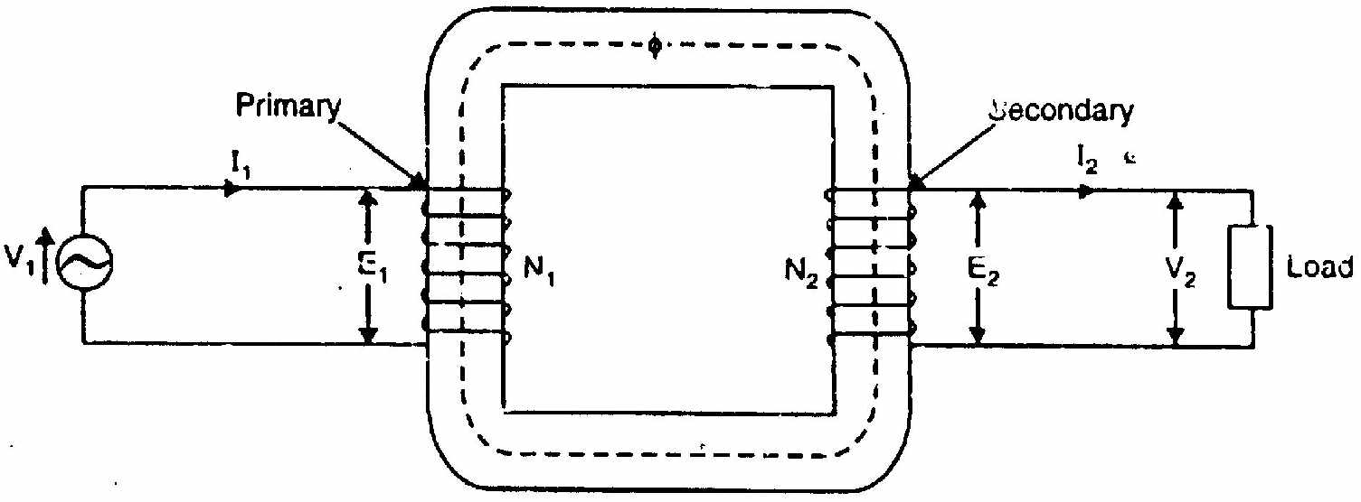
Primary side variables:
| Symbol | Description |
|---|---|
| v1(t), V1 | Instantaneous and RMS applied terminal voltage |
| i1(t), I1 | Instantaneous and RMS primary current |
| N1 | Number of primary turns |
| e1(t), E1=4.44fN1Φm | Self-induced counter-EMF (lags Φ by 90°) |
Secondary side variables:
| Symbol | Description |
|---|---|
| N2 | Number of secondary turns |
| e2(t), E2=4.44fN2Φm | Mutually induced EMF |
| v2(t), V2 | Secondary terminal voltage |
| i2(t), I2 | Secondary load current |
| ZL=RL+jXL | Load impedance |
Core variables:
| Symbol | Description |
|---|---|
| Φ(t)=Φmsinωt | Mutual core flux |
| Φm | Peak mutual flux (Wb) |
| f | Supply frequency (Hz) |
| K=N2/N1=E2/E1 | Transformation ratio |
(b) Explain the no-load operation of a 1-phase transformer with a neat phasor diagram. [06, CO1]
Operation at no-load (I2=0):
When primary voltage V1 is applied and the secondary is open, a small no-load current I0 flows in the primary. This current has two components:
-
Magnetizing component Im: In quadrature with V1 (lagging by 90°). Creates the alternating core flux Φm.
-
Core-loss component Ic: In phase with V1. Supplies hysteresis and eddy current losses in the core.
I0=Ic2+Im2,cosϕ0=I0Ic=V1I0W0
The core flux Φm induces: E1=4.44fN1Φm≈V1,E2=4.44fN2Φm=V2 (open secondary)
Phasor diagram (no-load):
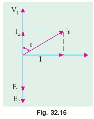
Key relationships:
- V1≈E1 (small I0R1 drop neglected for ideal core)
- V2=E2 (secondary open, no drop)
- V2/V1=N2/N1=K
Question 2
(a) Draw the phasor diagram of a R-L loaded ideal transformer, stating each step. [06, CO1]
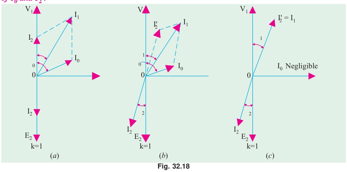
Ideal transformer assumptions: R1=R2=X1=X2=0, I0=0, so V2=E2 and V1=−E1.
For R-L load: secondary current lags secondary voltage by θ2=tan−1(XL/RL).
Step 1: Draw reference Φm horizontal (along +X axis).
Step 2: Draw E1 and E2 vertically downward (lagging Φm by 90°).
Step 3: Since ideal: V2=E2 (downward).
Step 4: R-L load: I2 lags V2 by θ2. Draw I2 clockwise from E2 by θ2.
Step 5: Ampere-turn balance: N1I1=−N2I2⇒I1=−(N2/N1)I2. So I1 is 180° opposite to I2.
Step 6: V1=−E1 (vertically upward, +Y direction).
Step 7: Angle between V1 and I1 is θ1=θ2. Primary power factor equals load power factor.
Phasor summary table:
| Phasor | Angle |
|---|---|
| Φm | 0° |
| E1,E2,V2 | −90° |
| V1 | +90° |
| I2 | −90°−θ2 |
| I1 | +90°−θ1 |
(b) Explain leakage flux and its effect on transformer operation. Include a schematic. [06, CO1]
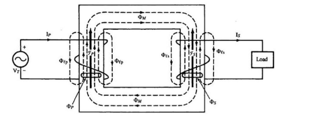
Three types of flux:
- ΦM (or Φm): Mutual flux through the iron core linking both primary and secondary windings. Transfers power.
- Φℓp (or Φl1): Primary leakage flux, linking only primary turns N1, completing path through air.
- Φℓs (or Φl2): Secondary leakage flux, linking only secondary turns N2, completing path through air.
Effects on operation:
-
Leakage reactances: Leakage flux Φl1∝I1 (air path, constant permeability). Induces self-EMF lagging current by 90°. Appears as series reactance: X1=2πfLl1,X2=2πfLl2
-
Voltage equations with leakage: V1=E1+I1R1+jI1X1 V2=E2−I2R2−jI2X2
-
Worsened voltage regulation: Under lagging pf load, reactive drop jI2X2 reduces V2.
-
Fault current limiting (beneficial): Short circuit fault current is limited by X01=X1+X2′.
Question 3
(a) Why are OC and SC tests preferred to direct load test for finding efficiency and voltage regulation of a transformer? [04, CO1]
Direct load test problems:
- Requires a full-rated load (resistive, inductive, or capacitive): difficult to arrange and expensive for large transformers.
- The load must absorb the full kVA during the test.
- Full losses must be supplied continuously. For a 500 kVA transformer, maintaining a full test for hours is costly and wasteful.
- The test gives results only at one load condition.
OC and SC test advantages:
- Low power consumption: OC test uses rated voltage but only no-load current (~2-10% of rated). SC test uses only ~5% of rated voltage. Power consumed is only the losses: orders of magnitude smaller.
- Economical: No large load needed.
- Accurate: Direct measurement of losses (core loss from OC, copper loss from SC). No estimation.
- Multiple results: Using these parameters, efficiency and VR can be calculated for any load and any power factor without repeating the test.
- Safe: No thermal stress from full-load currents sustained for long.
(b) 20 kVA, 2000/400V, OC test (HV open): 400V, 1.5A, 160W. SC test (LV short): 60V, rated I, 300W. Find: (i) parameters of equivalent circuit referred to HV side, (ii) efficiency and VR at full-load 0.8 pf lag. [08, CO1]
Turns ratio: a=2000/400=5
Rated HV current: I1,rated=20000/2000=10 A
OC test (LV side = secondary, 400V):
cosϕ0=V0I0W0=400×1.5160=600160=0.2667
Ic=1.5×0.2667=0.400 A,Im=1.5sin(cos−10.2667)=1.5×0.9638=1.446 A
Referred to HV side (×a2=25): Rc1=W0V0,HV2=16020002=25000Ω
Xm1=Im,HVV0,HV=1.446/52000=0.2892000=6920Ω
(Or: Rc1=a2Rc,LV=25×(4002/160)=25×1000=25000Ω ✓)
SC test (HV side):
R01=Isc2Wsc=102300=3.0Ω
Z01=IscVsc=1060=6.0Ω
X01=6.02−3.02=36−9=27=5.196Ω
Equivalent circuit parameters (referred to HV):
- Shunt: Rc1=25000Ω, Xm1=6920Ω
- Series: R01=3.0Ω, X01=5.196Ω
Efficiency at full load, 0.8 pf lag:
η=Scosϕ+PFe+PCu,FLScosϕ=16000+160+30020000×0.8=1646016000=97.20%
Voltage regulation at full load, 0.8 pf lag:
VR%=V1I1(R01cosϕ+X01sinϕ)×100
=200010(3.0×0.8+5.196×0.6)×100=200010(2.4+3.118)×100
=200010×5.518×100=200055.18×100=2.76%
Question 4
(a) Under assumptions of constant permeability and no leakage flux, derive the transformer EMF equation. [06, CO1]
Assumptions:
- Constant core permeability → constant reluctance → Φ∝I1 (linear magnetic circuit).
- Zero leakage flux → same flux Φ(t) links all N1 primary and N2 secondary turns.
Let: Φ(t)=Φmsin(2πft)
Primary EMF: e1(t)=−N1dtdΦ=−N1⋅2πfΦmcos(2πft)=N1(2πf)Φmsin(2πft−90°)
Peak: Em1=2πfN1Φm
RMS: E1=22πfN1Φm=2πfN1Φm=4.44fN1Φm
Secondary EMF: E1=4.44fN1Φm,E2=4.44fN2Φm
Alternative (form factor method):
In quarter-cycle (T/4=1/4f), flux rises from 0 to Φm: Avg EMF per turn=1/(4f)Φm=4fΦm
Form factor of sine wave: Kf=RMS/Avg=π/(22)=1.11
RMS EMF per turn =1.11×4fΦm=4.44fΦm
Multiply by turns: E1=4.44fN1Φm, E2=4.44fN2Φm ✓
(b) 50 Hz, 6.6 kV/400V transformer. Cross-section = 25 cm². Max flux density = 1.2 T. Find number of turns on each side. [03, CO1]
Peak flux: Φm=Bm×A=1.2×25×10−4=3×10⁻³ Wb=3 mWb
Primary turns (E1=V1=6600 V): N1=4.44fΦmE1=4.44×50×3×10−36600=0.6666600=9910 turns
Secondary turns (E2=V2=400 V): N2=4.44fΦmE2=0.666400=600 turns
Check: N1/N2=9910/600=16.52≈6600/400=16.5 ✓
(c) Obtain the equivalent circuit of a transformer referred to the primary side. [03, CO1]
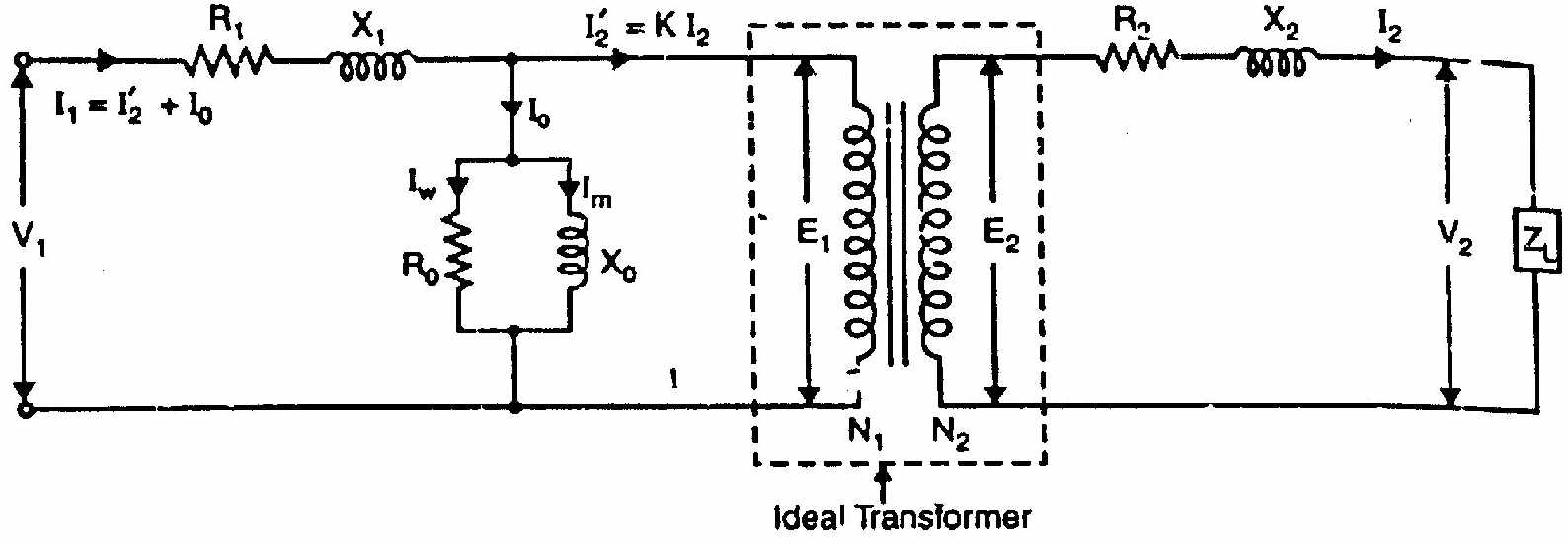
Referring secondary to primary:
Replace all secondary quantities with primary-referred (primed) values: R2′=a2R2,X2′=a2X2,E2′=aE2=E1,ZL′=a2ZL
Final equivalent circuit referred to primary:
Series branch: R01=R1+R2′, X01=X1+X2′ (total series impedance).
Shunt branch: Rc∥jXm (at primary terminals: approximate circuit).
In the approximate equivalent circuit, the shunt branch is moved to the primary input terminals (before R1, X1). This simplifies calculation without significant error for most power transformers.
Question 5
(a) A 3-phase IM is connected to a balanced 3-phase supply. Prove that the resultant flux produced by the stator currents is constant in magnitude (=1.5Φm) and rotates at synchronous speed. [08, CO2]
Setup: Stator windings 120° apart in space. Balanced 3-phase supply: ΦR=Φmsinωt,ΦY=Φmsin(ωt−120°),ΦB=Φmsin(ωt+120°)
Resolve into X (horizontal) and Y (vertical) components:
Take R-phase axis as +X. Y-phase axis is at 120° from X. B-phase axis is at 240° from X.
X-component: Φx=ΦR(1)+ΦYcos120°+ΦBcos240° =Φmsinωt+Φmsin(ωt−120°)(−21)+Φmsin(ωt+120°)(−21)
Using sin(A−B)+sin(A+B)=2sinAcosB: =Φmsinωt−21Φm⋅2sinωtcos120°=Φmsinωt−21Φm⋅2sinωt⋅(−21) =Φmsinωt+21Φmsinωt=23Φmsinωt
Y-component: Φy=ΦYsin120°+ΦBsin240° =Φmsin(ωt−120°)⋅23+Φmsin(ωt+120°)⋅(−23) =23Φm[sin(ωt−120°)−sin(ωt+120°)]
Using sin(A−B)−sin(A+B)=−2cosAsinB: =23Φm⋅(−2cosωtsin120°)=23Φm⋅(−2cosωt⋅23)=−23Φmcosωt
Magnitude: Φr=Φx2+Φy2=(23Φm)2(sin2ωt+cos2ωt)=23Φm=1.5Φm=constant
Space angle: θ=tan−1(ΦxΦy)=tan−1(sinωt−cosωt)=ωt−90°
dtdθ=ω=2πf⟹Ns=P120f rpm
Conclusion: Resultant flux = 1.5Φm (constant magnitude), rotating at synchronous speed Ns. (Proved)
(b) Show that the rotor copper loss = s× air gap power. Also show Pm:Pr,Cu:Pg=(1−s):s:1. [04, CO2]
From equivalent circuit, air-gap power: Pg=3I22⋅sR2
Rotor copper loss: Pr,Cu=3I22R2=s⋅3I22⋅sR2=s⋅Pg
Pr,Cu=sPg
Mechanical power: Pm=Pg−Pr,Cu=Pg−sPg=(1−s)Pg
Ratio: Pm:Pr,Cu:Pg=(1−s)Pg:sPg:Pg=(1−s):s:1
(Proved)
Question 6
(a) Derive the expression for maximum torque of a 3-phase IM and show it is independent of rotor resistance. [07, CO2]
Torque equation: T=R22+s2X22ksE22R2,k=2πns3
Condition for maximum torque:
Differentiate T with respect to s and equate to zero. Equivalently, maximize f(s)=R22+s2X22sR2.
Using quotient rule, setting numerator of df/ds to zero: R22+s2X22−2s2X22=0⟹R22=s2X22⟹smT=X2R2
Value of maximum torque:
Substitute s=smT=R2/X2 into the torque equation:
Numerator: smTE22R2=X2R2E22R2=X2R22E22
Denominator: R22+smT2X22=R22+X22R22X22=2R22
Tmax=k⋅2R22R22E22/X2=2X2kE22
R2 cancels completely. Tmax depends only on E2 (supply voltage) and X2 (standstill reactance).
Conclusion:
- Rotor resistance determines where max torque occurs: smT=R2/X2.
- Rotor resistance has no effect on the value of max torque: Tmax=kE22/(2X2).
- Adding rotor resistance in a wound-rotor motor shifts torque peak to higher slip without reducing it.
(Proved)
(b) 6-pole, 400V, 50 Hz, star-connected IM. R2′=0.5Ω, X2′=2.0Ω (standstill, referred to stator). Full-load slip = 4%. Find: starting torque, full-load torque, max torque, efficiency if mechanical losses = 500 W. [05, CO2]
Ns=6120×50=1000 rpm=350 rps
k=2π×50/33=104.723=0.02865
Phase voltage: Vϕ=400/3=231.0 V. Take E2′=Vϕ=231.0 V.
Starting torque (s=1): Tst=0.52+12×22k×1×2312×0.5=0.25+4.00.02865×53361×0.5=4.25764.7=179.9 N-m
Full-load torque (s=0.04): TFL=0.25+0.042×40.02865×0.04×53361×0.5=0.25+0.00640.02865×0.04×26680=0.256430.55=119.2 N-m
Maximum torque: Tmax=2X2kE22=2×2.00.02865×53361=4.01528.9=382.2 N-m
Efficiency at full load:
Air-gap power: Pg=TFL×ωs=119.2×(2π×1000/60)=119.2×104.72=12483 W
Rotor copper loss: Pr,Cu=sPg=0.04×12483=499.3 W
Mechanical power: Pm=(1−s)Pg=0.96×12483=11983 W
Net output: Pout=Pm−Pfric=11983−500=11483 W
Stator losses (PFe and PCu1) are not given. Assuming they are negligible (Pinput≈Pg):
Pinput≈12483 W
η=PinputPout×100≈1248311483×100=92.0%
Question 7
(a) Explain the no-load and blocked rotor tests for a 3-phase IM. From these tests, determine the equivalent circuit parameters. [09, CO3]
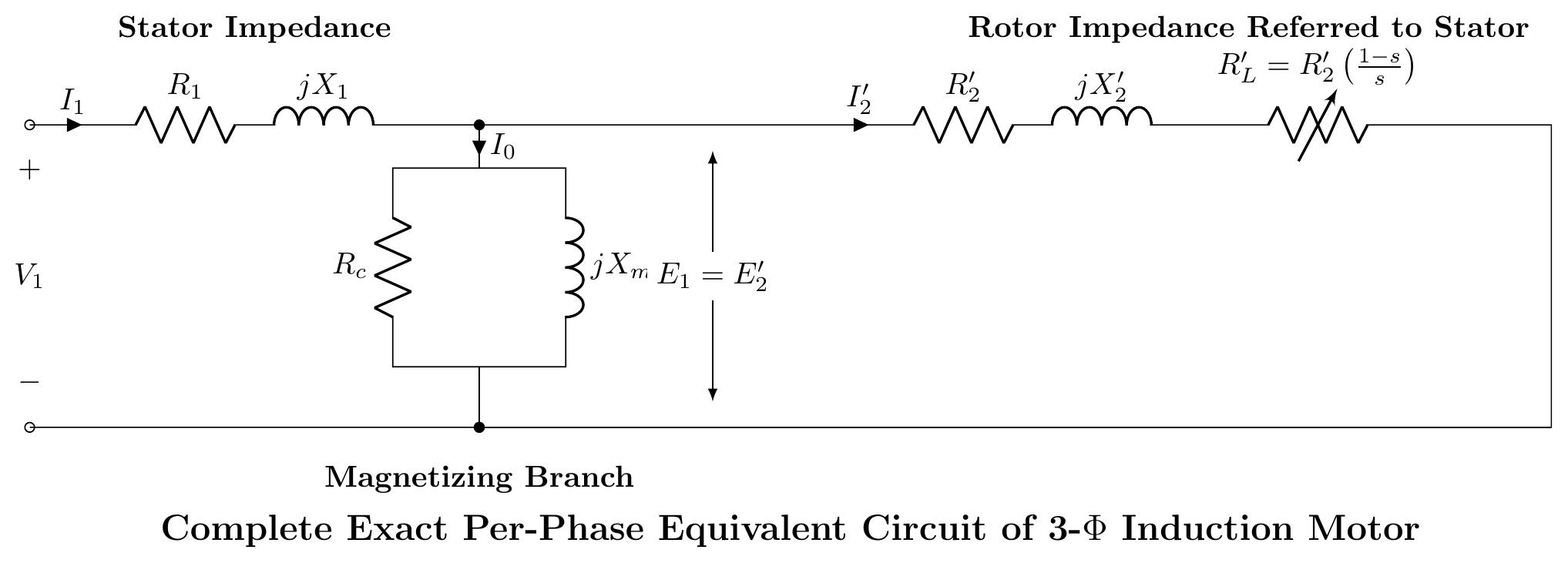
No-Load Test: Motor runs uncoupled at rated voltage and frequency. Since slip s≈0, the rotor branch is effectively an open circuit. The motor draws a small no-load current I0 to supply core loss and friction/windage loss.
- Measurements: V0 (line voltage), I0 (line current), P0 (3-phase power).
- Parameters found: Shunt branch (Rc, Xm). Rc=IcVϕ,Xm=ImVϕwhere Ic=I0cosϕ0,Im=I0sinϕ0
Blocked-Rotor Test: Rotor is mechanically blocked (s=1). A reduced voltage (10-15% of rated) is applied to circulate rated full-load current. At such low voltage, core loss is negligible. Input power equals full-load copper loss.
- Measurements: Vsc (line voltage), Isc (line current), Psc (3-phase power).
- Parameters found: Equivalent series resistance and reactance (R01,X01). Z01=IscVsc/3,R01=3Isc2Psc,X01=Z012−R012 Assuming X1=X2′=X01/2.
DC Test (for R2′): Measure stator resistance R1 using a DC source. Then rotor resistance referred to stator is R2′=R01−R1.
(b) Explain the effect of rotor resistance on the torque-speed characteristic curve. [03, CO3]
From smT=R2/X2 and Tmax=kE22/(2X2):
Increasing rotor resistance R2 (wound-rotor motor with external resistance):
- smT increases: the peak torque shifts to higher slip (lower speed).
- Tmax remains unchanged (no R2 in the formula).
- The starting torque Tst increases as R2 increases (up to the point R2=X2, at which Tst=Tmax).
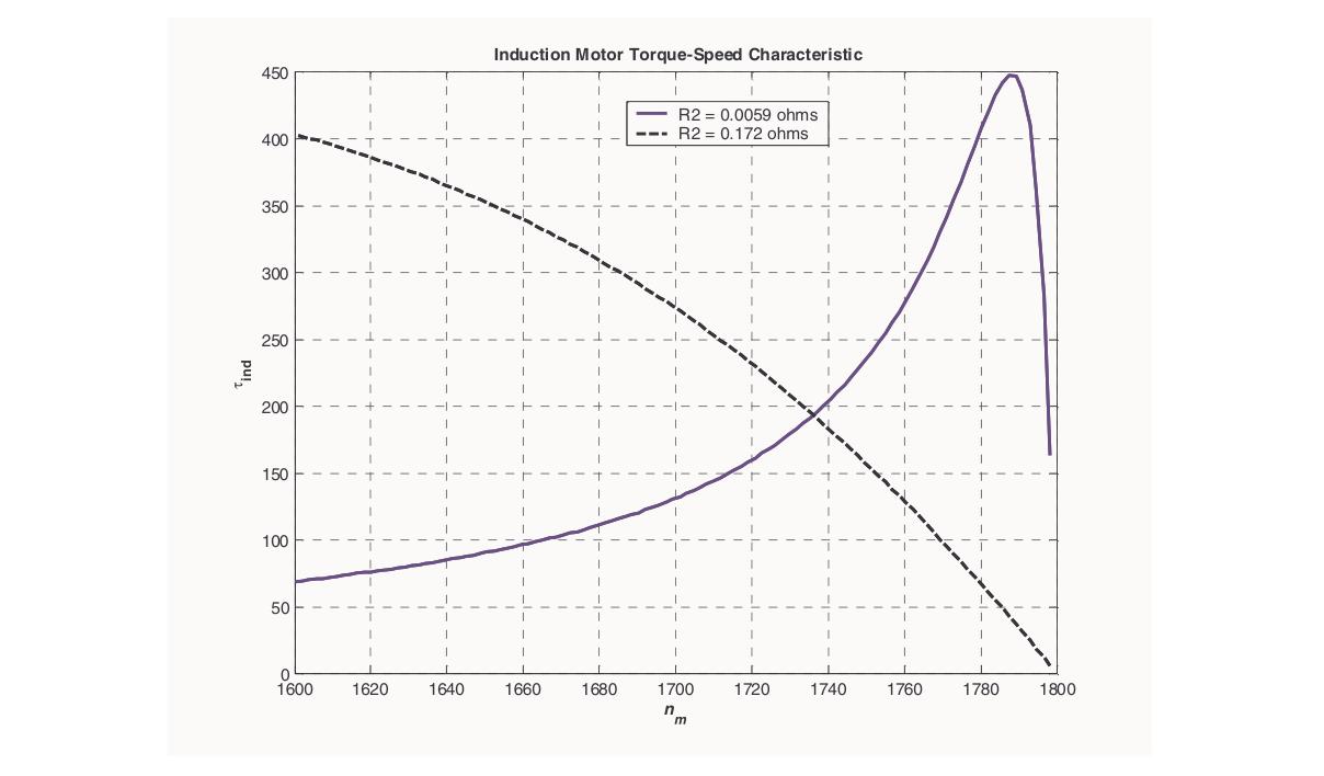
Practical use: By selecting appropriate external resistance, the wound-rotor motor can develop maximum torque at any desired speed. This is used for step-speed control and smooth starting of heavy loads.
Question 8
(a) Explain the principle of operation of a 1-phase induction motor and why it is not self-starting (with double revolving field theory). [06, CO4]
A single-phase induction motor has:
- One stator winding (main winding) carrying single-phase AC.
- A squirrel-cage rotor.
Why it is not self-starting:
A single-phase AC current creates a pulsating magnetic flux, not a rotating one: Φ=Φmsinωt
By the double revolving field theory (Ferraris theorem):
This pulsating field decomposes into two counter-rotating RMFs of equal magnitude Φm/2:
Φ=Forward field2Φmsin(ωt−θ)+Backward field2Φmsin(ωt+θ)
Each produces a torque on the squirrel-cage rotor:
- Forward field produces Tf (positive)
- Backward field produces Tb (negative)
At standstill (N=0): Both fields see the same slip (s=1). So Tf=Tb and net torque =0.
When running (pushed to forward speed N):
- Slip for forward field: sf=(Ns−N)/Ns (small)
- Slip for backward field: sb=(Ns+N)/Ns=2−sf (close to 2)
- Tf>Tb → motor continues running in the pushed direction.
Conclusion: Zero starting torque → not self-starting. The motor needs a starting mechanism.
(b) Describe two types of single-phase induction motors commonly used in practice. [06, CO4]
Type 1: Capacitor-Start, Capacitor-Run Motor (Two-Value Capacitor Motor):
This motor has:
- Main winding (M): always in circuit.
- Auxiliary winding (A): permanently in circuit.
- Starting capacitor Cs: in circuit only during starting (switched out by centrifugal switch after ~75% speed).
- Running capacitor Cr: permanently in circuit.
Starting: Cs+Cr (combined large capacitance) gives nearly 90° phase split between Im and Ia. High starting torque (200-350% of FL).
Running: Cs disconnected. Cr (smaller value) is optimized for running. Better running efficiency, power factor, and quieter operation compared to single capacitor motors.
Applications: Refrigerator compressors, pumps, air conditioners, power tools.
Type 2: Shaded-Pole Motor:
This is the simplest single-phase induction motor. It has:
- Salient poles (projecting poles like a DC machine).
- A short-circuited copper band (shading ring) placed around a portion of each pole face.
Operating principle:
The alternating flux in each pole induces a current in the shading ring. By Lenz's Law, this current opposes the flux change in the shaded portion. The flux in the shaded portion lags behind the flux in the unshaded portion in time, though they are in the same physical space. This time lag produces a sweeping effect from unshaded to shaded portion, like a weak rotating field. This gives a small, unidirectional starting torque.
The rotor (squirrel-cage) follows this sweeping field from unshaded → shaded, and keeps running.
Characteristics:
- Very low starting torque (40-60% of FL)
- Very low efficiency (copper ring always dissipates heat)
- Very simple and reliable: no capacitors, no switches, no auxiliary winding
- Only for small sizes (fans, relays, small appliances)
- Fixed rotation direction (cannot be reversed without mechanical modification)
Applications: Small cooling fans, hair dryers, small exhaust fans, record turntables, display motors.
Source: PrevYearQuestions/2024.md
← 2023 Answer | 🏠 Index | (end)