answers_exam_style/2023_answer.md
19.5 KB · commit d2f3b6e
← 2021 Answer | 🏠 Index | 2024 Answer →
ECE 2207: 2023 Semester Final: Exam Style Answers
RUET · ECE Dept · 2nd Year Even Semester (Session 2022-23) Course Code: ECE 2207 | Full Marks: 60 | Time: 3 Hours Attempt any 5 questions out of 8. All questions carry equal marks (12 each).
OBE Format Note: This is the new 60-mark OBE format. Each question is 12 marks, split into sub-parts linked to specific Course Outcomes (COs).
Question 1
(a) What is transformer? With a neat schematic diagram of a 1-φ transformer, identify and explain all the variables on both sides. [06, CO1]
Transformer: A static electromagnetic device that transfers electrical energy between two circuits at the same frequency but different voltage and current levels, via electromagnetic induction through a shared magnetic core.
Schematic:
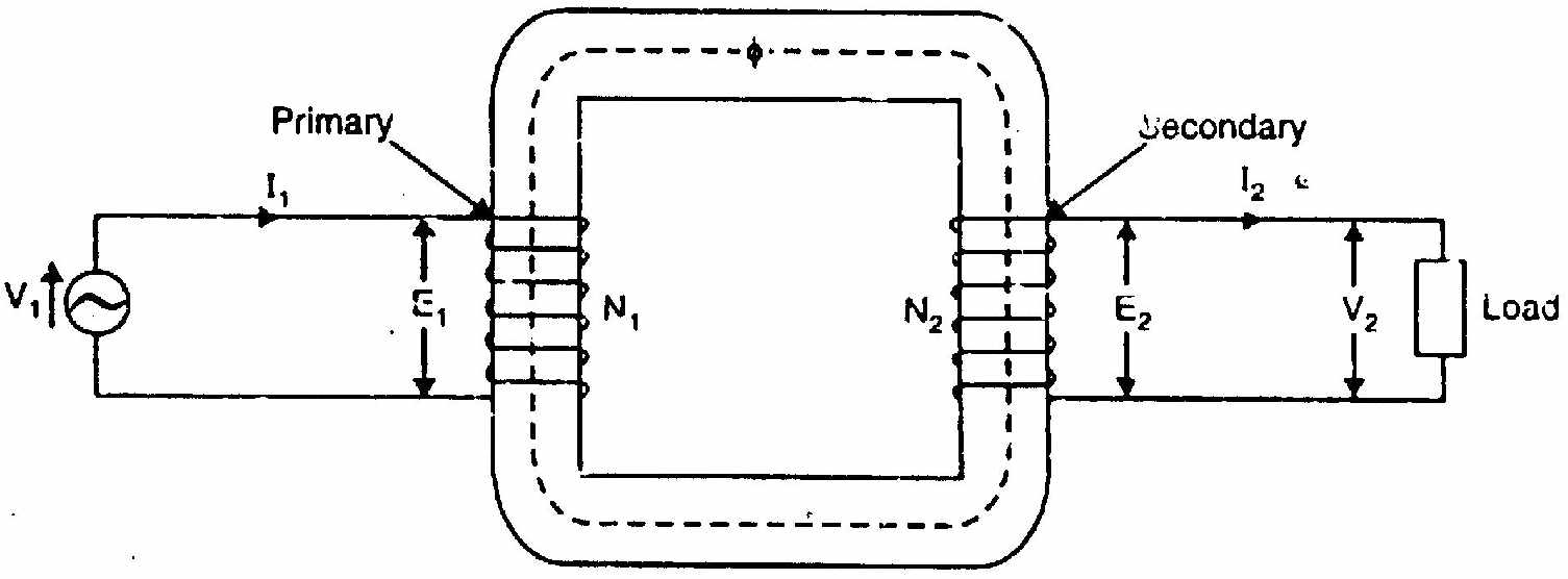
Variable Identification:
| Symbol | Name | Side |
|---|---|---|
| v1(t), V1 | Applied terminal voltage | Primary |
| i1(t), I1 | Primary current | Primary |
| N1 | Number of primary turns | Primary |
| e1(t), E1 | Self-induced counter-EMF | Primary |
| Φ(t) | Mutual core flux (Wb) | Core |
| Φm | Peak mutual flux | Core |
| N2 | Number of secondary turns | Secondary |
| e2(t), E2 | Mutually induced EMF | Secondary |
| v2(t), V2 | Secondary terminal voltage | Secondary |
| i2(t), I2 | Secondary load current | Secondary |
| ZL=RL+jXL | Load impedance | Secondary |
| K=N2/N1 | Transformation ratio | Both |
(b) Under the assumptions of an ideal transformer, prove that E1=4.44fN1Φm and E2=4.44fN2Φm. [06, CO1]
Assumptions:
- Core permeability is constant (no saturation). Core reluctance is constant.
- No leakage flux. Same flux Φ(t) links all turns of both windings.
Let core flux be: Φ(t)=Φmsin(ωt), where Φm = peak flux (Wb), f = supply frequency (Hz), ω=2πf.
For primary (N₁ turns):
By Faraday's Law: e1(t)=−N1dtdΦ=−N1⋅ωΦmcosωt=N1ωΦmsin(ωt−90°)
Peak value: Em1=N1ωΦm=2πfN1Φm
RMS value (sine wave, RMS = peak/2): E1=2Em1=22πfN1Φm=2πfN1Φm
Numerical constant: 2π=1.4142×3.1416=4.4429≈4.44
E1=4.44fN1Φm(Proved)
For secondary (N₂ turns):
Same flux Φ(t) links all N2 turns. By Faraday's Law: e2(t)=−N2dtdΦ=N2ωΦmsin(ωt−90°)
RMS: E2=4.44fN2Φm(Proved)
Both EMFs lag the mutual core flux by 90°.
Question 2
(a) A 100 kVA transformer, iron loss = 1 kW, full-load Cu loss = 1 kW. Distribution transformer load profile: 4h no-load, 12h half load, 8h full load. Find all-day efficiency. [06, CO1]
Energy output (kWh):
| Period | Output | Hours | kWh |
|---|---|---|---|
| No-load | 0 kW | 4 | 0 |
| Half load (at upf) | 50 kW | 12 | 600 |
| Full load (at upf) | 100 kW | 8 | 800 |
| Total | 24 | 1400 kWh |
Iron loss (24 hours, constant): WFe=1×24=24 kWh
Copper losses:
| Period | Cu loss | Hours | kWh |
|---|---|---|---|
| No-load | 0 | 4 | 0 |
| Half load | (0.5)2×1=0.25 kW | 12 | 3 |
| Full load | 1 kW | 8 | 8 |
| Total Cu | 11 kWh |
Total losses =24+11=35 kWh
Total input =1400+35=1435 kWh
ηall-day=14351400×100=97.56%
(b) OC test (secondary open): 220V, 0.8A, 80W. SC test (primary short): 12V, 10A, 40W. Transformer rated 2.2kV/220V. Find the equivalent circuit parameters referred to the secondary. [06, CO1]
From OC test (secondary/LV side):
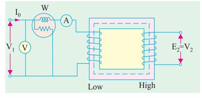
cosϕ0=V0I0W0=220×0.880=17680=0.4545
Ic=I0cosϕ0=0.8×0.4545=0.364 A
Im=I0sinϕ0=0.8×1−0.45452=0.8×0.8909=0.713 A
Referred to secondary: Rc2=IcV0=0.364220=604.4Ω
Xm2=ImV0=0.713220=308.6Ω
From SC test (primary/HV side shorted):
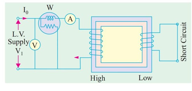
Turns ratio: a=2200/220=10
Rated secondary current: I2= rated → from SC test, Isc=10 A on secondary.
R02,sec=Isc2Wsc=10240=0.4Ω
Z02=IscVsc=1012=1.2Ω
X02=Z022−R022=1.44−0.16=1.28=1.131Ω
Equivalent circuit referred to secondary:
- Series: R02=0.4Ω, X02=1.131Ω
- Shunt: Rc2=604.4Ω, Xm2=308.6Ω
Question 3
(a) What is voltage regulation? Derive the expression for VR with neat phasor diagrams for lagging, unity, and leading pf loads. [08, CO1]
Voltage Regulation (VR): The change in secondary terminal voltage from no-load to full-load, as a percentage of the rated full-load secondary voltage, with primary voltage held constant.
VR%=V2,FLV2,NL−V2,FL×100%
Derivation (approximate formula):
From the equivalent circuit, secondary terminal voltage referred to primary: V1=V2′+I2′R01cosϕ2+I2′X01sinϕ2+j(…)≈V2′+I2′(R01cosϕ2±X01sinϕ2)
where + for lagging, − for leading.
No-load voltage: V2,NL≈V1/a=V2′
Full-load voltage: V2,FL=V2′
Using phasor: VR%≈V2,ratedI2(R01cosϕ+X01sinϕ)×100(lagging, positive)
VR%≈V2,ratedI2(R01cosϕ−X01sinϕ)×100(leading, can be negative)
Phasor diagrams:
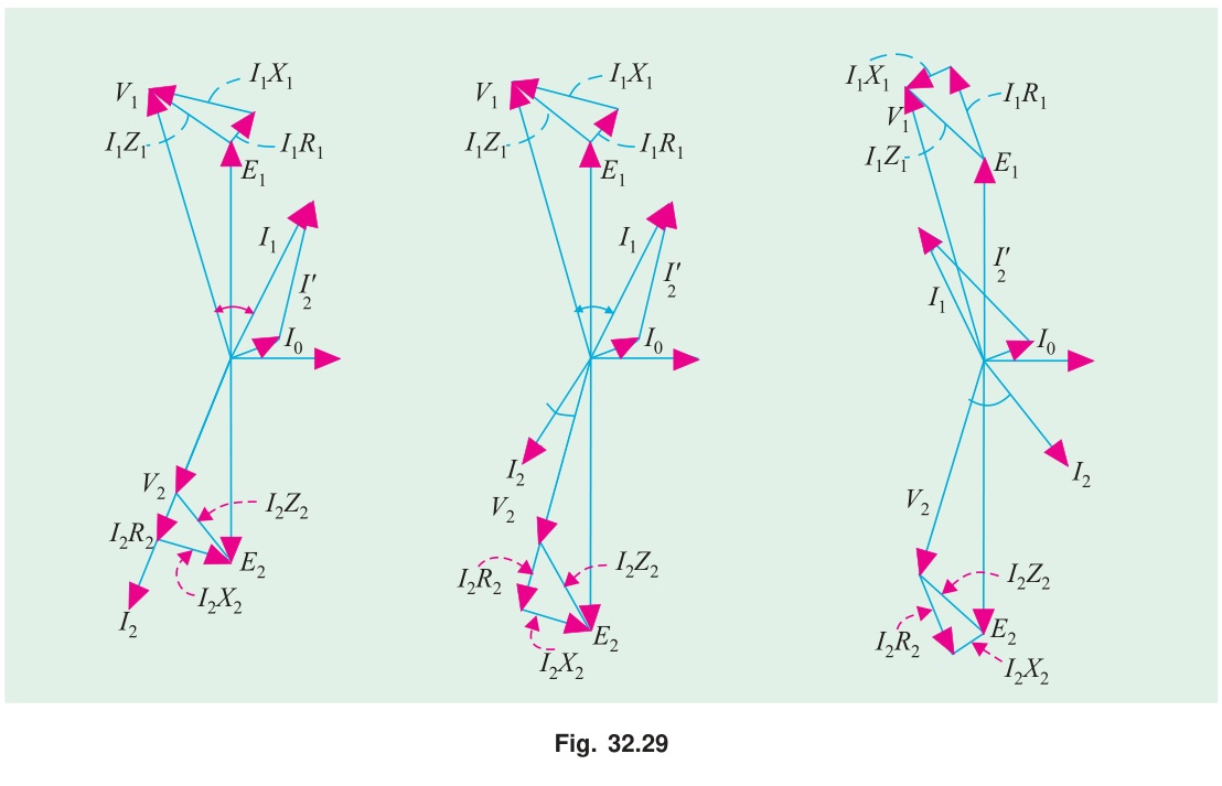
Lagging pf: V2 reference. I2 lags V2 by ϕ. V1=V2+I2R01∠0°+I2X01∠90°. ∣V1∣>∣V2∣. VR > 0.
Unity pf: I2 in phase with V2. Drop is only I2R01 (purely resistive). ∣V1∣ slightly greater. VR > 0 but small.
Leading pf: I2 leads V2 by ϕ. Reactive drop partially cancels resistive drop. ∣V1∣ may be less than ∣V2∣. VR can be negative (secondary voltage rises with load).
(b) 3300/220V, 50Hz, 50 kVA transformer. Winding resistance: primary = 3.96Ω, secondary = 0.0176Ω. Leakage reactance: primary = 15.8Ω, secondary = 0.07Ω. Find VR at 0.8 pf lagging. [04, CO1]
Turns ratio: a=3300/220=15
Refer to primary: R01=R1+a2R2=3.96+225×0.0176=3.96+3.96=7.92Ω
X01=X1+a2X2=15.8+225×0.07=15.8+15.75=31.55Ω
Rated primary current: I1=330050000=15.15 A
VR at 0.8 pf lag (cosϕ=0.8, sinϕ=0.6): VR%=V1I1(R01cosϕ+X01sinϕ)×100
=330015.15(7.92×0.8+31.55×0.6)×100
=330015.15(6.336+18.93)×100=330015.15×25.266×100
=3300382.78×100=11.6%
Question 4
(a) Explain what happens to a 3-phase Δ-Δ transformer bank when one transformer is damaged. Show 3-phase power can still be served. Also prove the capacity reduces to 57.7%. [08, CO1]
Event: One transformer (say TCA) in the Δ-Δ bank fails.
Why 3-phase power still reaches the load:
The primary and secondary delta loops still have two active transformers: TAB and TBC.
On the primary delta: The 3-phase supply maintains VAB and VBC. KVL in the delta loop demands VCA=−(VAB+VBC). Even without TCA, this voltage is present at the open terminal.
On the secondary delta: TAB produces Vab=K⋅VAB. TBC produces Vbc=K⋅VBC. By KVL: Vca=−(Vab+Vbc)=K⋅VCA. All three secondary line voltages exist and are balanced.
Three-phase balanced power is delivered by two transformers. This configuration is called the open-delta (V-V) connection.
Capacity proof:
Let each single transformer be rated S=VI kVA.
In closed-Δ (3 transformers): Total =3S kVA.
In open-Δ (2 transformers): Each transformer still carries rated current I at rated voltage V. For a balanced 3-phase unity pf load, each transformer operates at power factor cos30°=3/2.
Sopen=2×V×I×cos30°=2VI×23=3VI=3S
SclosedSopen=3S3S=31=0.577=57.7%
Utilization factor of each transformer in open-Δ: The transformer is rated S=VI kVA but works at power factor cos30°=0.866, delivering only 0.866S kW. So the utilization is 86.6% instead of 100%.
(b) Conditions for parallel operation. [04, CO1]
- Same voltage ratio (same primary/secondary rated voltages).
- Same per-unit impedance (for proportional load sharing).
- Same polarity (same instantaneous phase relationship at terminals).
- Same phase sequence (3-phase transformers only).
- Same vector group: zero phase angle between secondary voltages.
Question 5
(a) For a 3-phase induction motor, derive the torque expression and show that the torque-slip relationship is: T=R22+s2X22ksE22R2 where k=2πns3. [08, CO2]
At running slip s, per-phase rotor quantities:
- Rotor induced EMF: E2s=sE2
- Rotor reactance: X2s=sX2
- Rotor current: I2=R22+s2X22sE2
- Rotor power factor: cosϕ2=R22+s2X22R2
Air-gap power (power transferred to rotor):
Pg=3E2sI2cosϕ2=3⋅sE2⋅R22+s2X22sE2⋅R22+s2X22R2
Pg=R22+s2X223s2E22R2
Alternatively, using the equivalent circuit representation R2/s:
Pg=3I22⋅sR2=3⋅R22+s2X22s2E22⋅sR2=R22+s2X223sE22R2
Torque from air-gap power:
Synchronous speed in rps: ns=Ns/60. Angular synchronous speed: ωs=2πns.
T=ωsPg=2πnsPg=(R22+s2X22)⋅2πns3sE22R2
T=R22+s2X22ksE22R2,k=2πns3
(Derived)
(b) 8-pole, 50 Hz, 3-phase IM. Full-load slip = 2.5%. R2=0.4Ω, X2=2.0Ω (standstill). Find: slip and speed at maximum torque, ratio Tmax/TFL. [04, CO2]
Ns=8120×50=750 rpm
Slip at max torque: smT=X2R2=2.00.4=0.2
Speed at max torque: NmT=Ns(1−smT)=750(1−0.2)=600 rpm
Torque ratio: Using a=smT=0.2, sf=0.025:
TmaxTf=a2+sf22asf=0.04+0.0006252×0.2×0.025=0.0406250.010=0.246
TfTmax=0.2461=4.07
Question 6
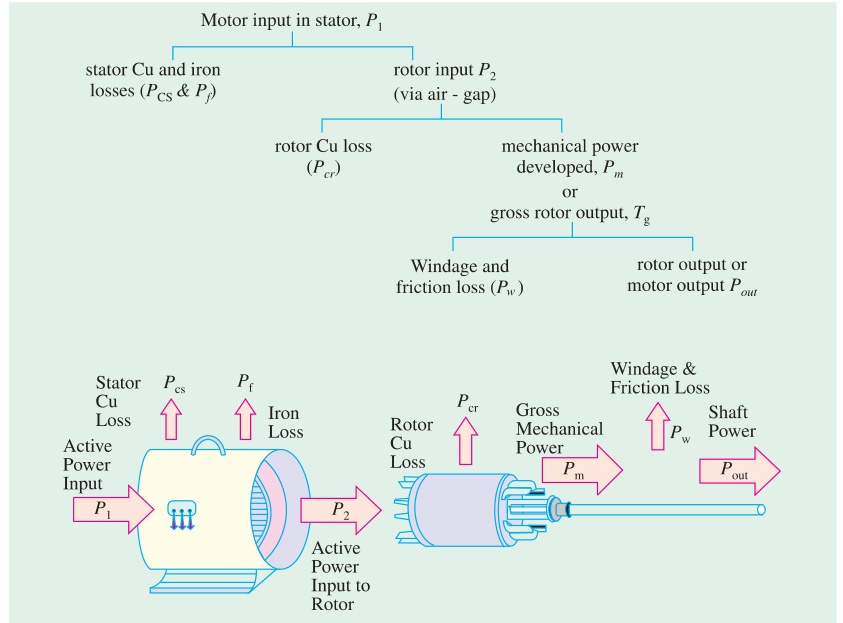
(a) For a 3-phase IM, derive: Pg:Pr,Cu:Pm=1:s:(1−s). Draw the complete power flow diagram. [06, CO2]
From equivalent circuit, rotor quantities:
Rotor current: I2=R22+s2X22sE2
Air-gap power: Pg=3I22⋅sR2
Rotor copper loss: Pr,Cu=3I22R2=s⋅(3I22sR2)=s⋅Pg
Mechanical power: Pm=Pg−Pr,Cu=Pg−sPg=(1−s)Pg
Therefore: Pg:Pr,Cu:Pm=1:s:(1−s)
Power flow diagram:
(b) How can we improve the poor power factor of an induction motor at light loads? [03, CO2]
At light load, the motor draws mostly magnetizing current (reactive). The working (active) component is small. So the power factor is very low.
Methods to improve power factor:
- Avoid running at no-load or very light load: Switch off motors that are idling.
- Capacitor banks: Connect shunt capacitors at the motor terminals. Reactive current from capacitors offsets the lagging reactive current of the motor.
- Use appropriately sized motor: An oversized motor at light load has low pf. Match motor size to load requirement.
- Synchronous condenser: A synchronous motor running at no-load (overexcited) supplies reactive power to the system.
- Variable frequency drive (VFD): Reduces voltage at light load, which reduces flux and reduces magnetizing current. Improves efficiency and pf at light loads.
(c) What is rotor efficiency? Show that rotor efficiency = (1−s). [03, CO2]
Rotor efficiency: Ratio of mechanical power developed to electrical power input to the rotor (air-gap power).
ηrotor=PgPm=Pg(1−s)Pg=(1−s)
From the power ratio Pg:Pr,Cu:Pm=1:s:(1−s):
- Of each unit of air-gap power, fraction s is wasted as rotor copper heat.
- Fraction (1−s) becomes mechanical work.
At s=0.04 (full load, typical): ηrotor=96%. High rotor efficiency is achievable at low slip. Motors are designed to run at small slip for this reason.
Question 7
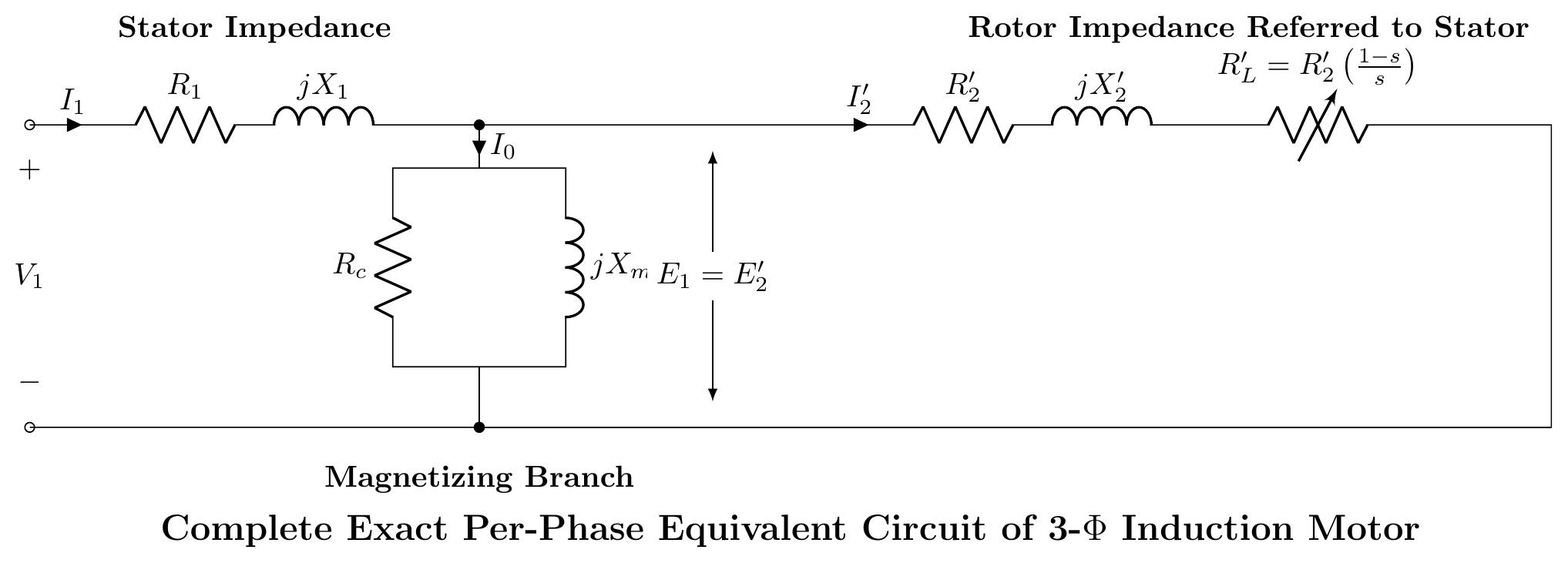
(a) Explain the no-load and blocked rotor tests of a 3-phase induction motor. [08, CO3]
No-Load Test: Motor runs uncoupled at rated voltage and frequency. Since slip s≈0, the rotor branch is effectively an open circuit. The motor draws a small no-load current I0 to supply core loss and friction/windage loss.
- Measurements: V0 (line voltage), I0 (line current), P0 (3-phase power).
- Parameters found: Shunt branch (Rc, Xm). Rc=IcVϕ,Xm=ImVϕwhere Ic=I0cosϕ0,Im=I0sinϕ0
Blocked-Rotor Test: Rotor is mechanically blocked (s=1). A reduced voltage (10-15% of rated) is applied to circulate rated full-load current. At such low voltage, core loss is negligible. Input power equals full-load copper loss.
- Measurements: Vsc (line voltage), Isc (line current), Psc (3-phase power).
- Parameters found: Equivalent series resistance and reactance (R01,X01). Z01=IscVsc/3,R01=3Isc2Psc,X01=Z012−R012 Assuming X1=X2′=X01/2.
DC Test (for R2′): Measure stator resistance R1 using a DC source. Then rotor resistance referred to stator is R2′=R01−R1.
(b) A 3-phase star-connected IM, SC test gives: V=75 V, I=38 A, P=4 kW. Stator resistance per phase = 0.5Ω. Find: R2′, X1, X2′. [04, CO3]
From SC test (star-connected, 3-phase):
Per-phase voltage: Vsc,ϕ=75/3=43.30 V
Z01=IscVsc,ϕ=3843.30=1.140Ω
R01=3Isc2Psc=3×3824000=43324000=0.923Ω
X01=Z012−R012=1.1402−0.9232=1.300−0.852=0.448=0.669Ω
R2′=R01−R1=0.923−0.5=0.423Ω
X1=X2′=2X01=20.669=0.335Ω
Question 8
(a) Explain the principle of operation of a 1-phase induction motor using the double revolving field theory. [06, CO4]
A single-phase stator with alternating current i=Imsinωt creates a pulsating magnetic flux along one fixed axis: Φ=Φmsinωt
Double revolving field theory (Ferraris theorem):
This pulsating flux is mathematically equivalent to two equal halves rotating in opposite directions:
Φ=2Φmsin(ωt−θ)+2Φmsin(ωt+θ)
- Forward field (Φf): Magnitude Φm/2, rotates at +Ns rpm (forward).
- Backward field (Φb): Magnitude Φm/2, rotates at −Ns rpm (backward).
Each rotating field interacts with the squirrel-cage rotor, producing an induction torque just like in a 3-phase motor.
At standstill (s=1):
For forward field: slip sf=1 For backward field: slip sb=(2−s)=(2−1)=1
Both fields produce equal and opposite torques: Tf(s=1)=Tb(s=1)
Net torque =Tf−Tb=0. Motor cannot self-start.
When running (pushed to speed N):
Forward slip: sf=(Ns−N)/Ns=s (small) Backward slip: sb=(Ns+N)/Ns=2−s (nearly 2)
For small s: Tf is in the stable high-torque region, Tb is in the low-torque high-slip region.
Tf>Tb⟹Net forward torque>0
Motor continues to run. The direction of running is determined by the initial push.
(b) Describe any two methods of making a 1-phase IM self-starting. [06, CO4]
Method 1: Capacitor-Start Motor:
An auxiliary (starting) winding is placed 90° apart in space from the main winding. A capacitor is connected in series with the auxiliary winding. The capacitor advances the phase of auxiliary winding current. With the right capacitor value, the auxiliary current Ia leads the main current Im by nearly 90° in time.
The 90° time-phase split + 90° space-phase split produces a rotating magnetic field. This generates a starting torque.
Once the motor reaches ~75% of synchronous speed, a centrifugal switch disconnects the auxiliary winding + capacitor. The motor continues on the main winding.
Starting torque: 200-400% of full-load torque.
Advantages: High starting torque, relatively quiet.
Disadvantages: Centrifugal switch is a wear component. Capacitor adds cost.
Method 2: Shaded-Pole Motor:
A short-circuited copper band (shading band) is placed around a portion of each stator pole face.
When alternating flux through the pole increases, the shading band opposes the change (Lenz's Law). Flux in the shaded portion lags behind flux in the unshaded portion. This creates a phase difference between the two portions of each pole.
The non-uniform, time-shifted flux produces a weak rotating effect across the pole face. This gives a small starting torque, and the motor starts rotating from the unshaded to the shaded portion of the pole.
Advantages: Extremely simple, no switches or capacitors. Very reliable. Cheap.
Disadvantages: Very low starting torque (typically 40-50% of FL). Low efficiency (copper band always dissipates energy). Low power factor. Small sizes only (fans, small appliances).
Source: PrevYearQuestions/2023.md