answers_exam_style/2021_answer.md
26.0 KB · commit d2f3b6e
← 2020 Answer | 🏠 Index | 2023 Answer →
ECE 2207: 2021 Semester Final: Exam Style Answers
RUET · ECE Dept · 2nd Year Odd Semester 2021 Full Marks: 72 · Time: 3 Hours · Attempt any 6 (3 from each section)
SECTION - A (Transformers: Q1 to Q4)
Question 1
(a) What are the characteristics of an ideal transformer? [03]
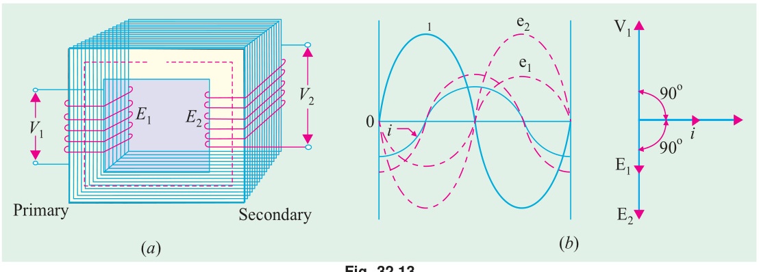
An ideal transformer has the following assumptions:
- Zero winding resistance: Both primary and secondary windings have no resistance (R1=R2=0). No copper losses.
- Zero leakage flux: All magnetic flux is confined to the core. No flux leakage into air. Both windings link exactly the same flux.
- Infinite core permeability: No magnetizing current is needed to set up the core flux (Im=0).
- Zero core losses: No hysteresis or eddy current losses in the core.
- Constant flux: Core flux Φ is sinusoidal and remains constant regardless of load.
- 100% efficiency: No losses of any kind. All input power transfers to the output.
- Transformation ratio: V1/V2=N1/N2=I2/I1=a
(b) Derive the equation for RMS EMF induced in both primary and secondary windings. Show EMF/turn is the same in both. [05]
Let core flux: Φ(t)=Φmsin(ωt). Same flux links all turns of both windings (no leakage).
Primary induced EMF:
By Faraday's Law: e1(t)=−N1dtdΦ=−N1ωΦmcos(ωt)=N1ωΦmsin(ωt−90°)
Peak value: Em1=N1ωΦm=2πfN1Φm
RMS value: E1=2Em1=22πfN1Φm=2πfN1Φm
Since 2π=4.44: E1=4.44fN1Φm
Secondary induced EMF: Same Φ(t) links all N2 secondary turns:
e2(t)=−N2dtdΦ=N2ωΦmsin(ωt−90°)
RMS: E2=4.44fN2Φm
EMF per turn: N1E1=4.44fΦm=N2E2
EMF per turn =4.44fΦm for both windings. (Proved)
(c) 25 kVA transformer, 500/50 turns, primary on 3000V/50Hz supply. Find: full-load primary and secondary currents, secondary EMF, maximum flux in core. [04]
Given: S=25 kVA, N1=500, N2=50, V1=3000 V, f=50 Hz
Turns ratio: a=N2N1=50500=10
Secondary EMF: E2=aE1=aV1=103000=300 V
Full-load currents: I1=V1S=300025000=8.33 A
I2=V2S=30025000=83.3 A
Maximum flux: From E1=4.44fN1Φm: Φm=4.44fN1E1=4.44×50×5003000=1110003000=27.03 mWb
Question 2
(a) Draw the phasor diagram of transformer considering winding resistance and leakage reactance. [04]
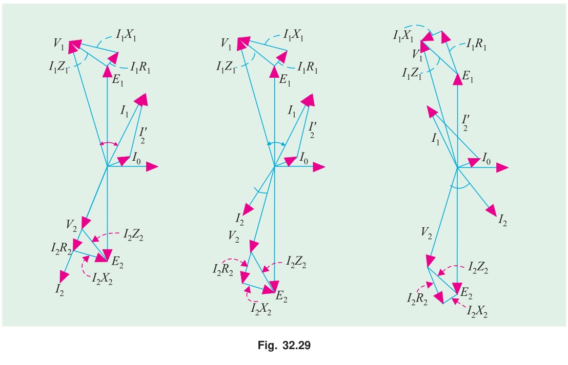
- Reference: Φm horizontal (+X axis).
- Induced EMFs: E1 and E2 pointing downward (lag Φm by 90°).
- Secondary terminal voltage: V2=E2−I2R2−jI2X2 (draw from tip of E2, subtract drops).
- Secondary current: I2 lags V2 by ϕ2 (load power factor angle).
- No-load current: I0=Ic−jIm (in phase with E1 component and lagging component).
- Primary current: I1=I0+I2′ where I2′=(N2/N1)I2.
- Primary voltage: V1=E1+I1R1+jI1X1 (draw from tip of E1, add drops).
The angle between V1 and I1 gives the primary power factor angle ϕ1.
(b) Explain the procedure of the no-load test of a transformer. Why is this test performed? [04]
Procedure:
- Keep secondary (HV) side open-circuited.
- Apply rated voltage to the primary (LV) side via a variac.
- Connect measuring instruments on the primary side: voltmeter (V0), ammeter (I0), wattmeter (W0).
- Record readings when supply reaches rated value: V0=Vrated, I0, W0.
Calculations:
Core loss: PFe=W0 (constant, independent of load)
cosϕ0=V0I0W0,Ic=I0cosϕ0,Im=I0sinϕ0
Rc=IcV0,Xm=ImV0
Turns ratio check: a=V1/V2 (measure both voltages)
Why this test is performed:
- To measure core (iron) losses: constant at all loads.
- To determine shunt branch parameters (Rc and Xm) of the equivalent circuit.
- To verify the turns ratio.
- To calculate no-load current and power factor.
The test is economical: rated voltage is applied but rated current does not flow (only 2–10%). Power consumption during the test is low.
(c) 20 kVA, 2400/240V, 50 Hz transformer. SC test (HV side): V=72 V, W=275 W, I= rated. Find constants referred to HV side and voltage regulation at 0.8 pf lag. [04]
Rated HV current: I1=240020000=8.33 A
From SC test (HV side): R01=Isc2Wsc=8.332275=69.39275=3.964Ω
Z01=IscVsc=8.3372=8.643Ω
X01=Z012−R012=8.6432−3.9642=74.70−15.71=58.99=7.681Ω
Voltage regulation at 0.8 pf lag (cosϕ=0.8, sinϕ=0.6): VR%=V1I1(R01cosϕ+X01sinϕ)×100
=24008.33(3.964×0.8+7.681×0.6)×100
=24008.33(3.171+4.609)×100=24008.33×7.780×100
=240064.81×100=2.70%
Question 3
(a) Limitations of Y-Y connected transformer. How to overcome them? [03]
Limitations:
-
Third harmonic voltages: The magnetizing current of a transformer is non-sinusoidal: it contains third harmonics. In a Y-Y transformer, the neutral point is not usually connected. Third harmonic currents have no path to flow (they are zero-sequence). As a result, third harmonic EMFs appear in the line-to-neutral voltages, causing waveform distortion.
-
Voltage unbalance: Under unbalanced loads, the neutral point shifts. This causes unequal voltage distribution among phases.
-
No phase shift: Y-Y gives 0° phase displacement. This limits flexibility in interconnection with other transformer groups.
How to overcome:
-
Connect the neutral to ground (4-wire system): Allows zero-sequence (third harmonic) currents to flow. Eliminates harmonic voltages in phase-to-neutral voltages.
-
Add a delta-connected tertiary winding: The delta provides a closed circulating path for third harmonic currents. This suppresses harmonic voltages without requiring a grounded neutral.
-
Use Δ winding on at least one side (Y-Δ or Δ-Y connection): Inherently eliminates third harmonic voltage problems.
(b) Is it possible to continue 3-phase power if one transformer is damaged? Justify and describe one technique. [06]
Yes: it is possible using the open-delta (V-V) connection.
Justification:
In a Δ-Δ bank of three single-phase transformers, if one fails, the remaining two can be reconnected in open-delta. Three-phase voltages remain balanced. Load can be served, but at only 57.7% of the original bank capacity.
How it works:
Let transformers TAB, TBC, TCA form the bank. Remove TCA.
Primary side: The three line voltages are fixed by the 3-phase supply. Even with TCA open, VAB and VBC still exist. By KVL around the delta loop: VCA=−(VAB+VBC): so the voltage across the open TCA position is also defined. But no transformer carries this voltage.
Secondary side: TAB produces secondary voltage Vab=K⋅VAB. TBC produces Vbc=K⋅VBC. By KVL: Vca=−(Vab+Vbc)=K⋅VCA. All three secondary voltages exist and are balanced.
Capacity reduction:
Each remaining transformer operates at rated voltage and rated current, but the load power factor for each differs from the closed-delta case. Net 3-phase output: Sopen−Δ=3×Ssingle transformer=0.577×3Ssingle=57.7% of closed-Δ
Practical importance: Used during maintenance (one transformer removed for repair) without interrupting supply.
(c) Draw the complete torque-speed curve of an induction motor. [03]
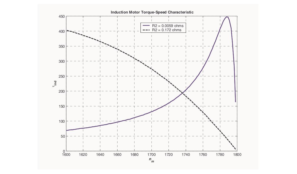
- At N=0 (s = 1): Starting torque Tst (positive, typically 1.5-2x full-load torque).
- Torque increases as speed increases from 0, reaching maximum Tmax (pull-out torque) at speed NmT=Ns(1−R2/X2).
- After Tmax, torque decreases rapidly as speed approaches Ns.
- At N=Ns (s = 0): Torque = 0.
- Beyond Ns (s < 0, negative slip): Machine acts as induction generator: negative torque (braking).
- At N<0 (plugging region, s > 1): Torque is positive but motor is in plugging mode.
Mark: Full-load operating point at about 95-98% of Ns, Tmax at NmT, starting torque at N=0.
Question 4
(a) Conditions for parallel operation of two 3-phase transformers. [04]
-
Same voltage ratio: Primary and secondary rated voltages must be equal. Otherwise a circulating current flows in the secondary loop even at no load.
-
Same per-unit (or percentage) impedance: Ensures load sharing is proportional to rated kVA. If impedances differ, the transformer with lower impedance takes a disproportionate share and may overload.
-
Same polarity: Corresponding terminals must have the same instantaneous polarity. For 3-phase, this means the same phase sequence of secondary voltages.
-
Same phase sequence: Both transformers must be connected to the same phase sequence (A-B-C). A reversed sequence causes a voltage difference and large circulating currents.
-
Same vector group (zero phase displacement): Both transformers must have the same vector group or have zero phase angle between their secondary voltages. A 30° phase difference (e.g., Yy0 with Yd11) causes very large circulating currents.
(b) What methods can be used for generating magnetic field? [04]
Magnetic fields can be generated by several methods:
-
Permanent magnets: Iron, alnico, neodymium magnets produce static fields. Used in BLDC motors, PMSMs, speakers.
-
DC electromagnets: DC current through a coil wound on an iron core creates a constant magnetic field. Used in synchronous motors, DC machines, relays.
-
AC electromagnets: Alternating current through a coil creates a pulsating magnetic field. Used in transformer cores, AC contactors.
-
Rotating magnetic field (3-phase windings): Three-phase AC currents in three spatially displaced windings create a continuously rotating field of constant magnitude. Used in 3-phase induction and synchronous motors.
-
Rotating magnetic field (2-phase): Two-phase currents (90° apart) in windings 90° apart in space produce a rotating field. Less common, used in some servo systems.
-
Single-phase with auxiliary winding: Capacitor or resistance creates phase split, giving a rotating field. Used in single-phase induction motors.
(c) 4-pole, 50 Hz slip-ring IM. R2=0.30Ω/phase, runs at 1440 rpm full load. Find external resistance to lower speed to 1320 rpm at same torque. [04]
Given: P=4, f=50 Hz, R2=0.30Ω, N1=1440 rpm (full load)
Ns=4120×50=1500 rpm
Full-load slip: s1=15001500−1440=150060=0.04
New slip at 1320 rpm: s2=15001500−1320=1500180=0.12
Condition for same torque at both operating points:
From the torque equation, at constant torque (and ignoring the s2X22 term for small slip, or using the proportionality at low slip):
T∝Rtotal2sE22Rtotal=RtotalsE22
For constant torque: R2s1=R2+Rexts2
0.300.04=0.30+Rext0.12
0.30+Rext=0.040.12×0.30=0.040.036=0.90Ω
Rext=0.90−0.30=0.60Ω/phase
SECTION - B (Induction Motors: Q5 to Q8)
Question 5
(a) For an IM, define: (i) Synchronous speed, (ii) Slip, (iii) Slip speed. [03]
(i) Synchronous speed (Ns): The speed of the rotating magnetic field produced by the 3-phase stator winding. Ns=P120f rpm
(ii) Slip (s): The fractional difference between synchronous speed and rotor speed. Expressed as a per-unit value or percentage. s=NsNs−N Range: s=1 at standstill, s≈0.02–0.05 at full load.
(iii) Slip speed: The actual speed difference between the rotating field and the rotor: Nslip=Ns−N=s⋅Ns rpm
This is the speed at which the rotor bars cut the rotating field, determining the induced EMF magnitude.
(b) Determine the starting torque of an IM. [04]
Starting torque is the torque developed when the rotor is at standstill (s=1).
From the general torque equation at s=1:
Tst=R22+(1)2X22k⋅1⋅E22R2=R22+X22kE22R2
where k=2πNs3 and E2 is standstill rotor EMF per phase.
Effect of rotor resistance on starting torque:
To find the rotor resistance R2 that maximizes starting torque: dR2dTst=0⟹R22+X22−2R22=0⟹R2=X2
Maximum starting torque (at R2=X2): Tst,max=X22+X22kE22X2=2X2kE22
This equals Tmax: the maximum running torque. In wound-rotor motors, external resistance is added to achieve Rtotal=X2 for maximum starting torque.
(c) Show that 2-phase supply produces a rotating magnetic field at synchronous speed. [05]
Setup: Two windings placed 90° apart in space. A balanced 2-phase supply: ia=Imsinωt,ib=Imsin(ωt−90°)=−Imcosωt
Each winding produces a pulsating flux along its axis: Φa=Φmsinωt(along X-axis) Φb=Φmsin(ωt−90°)=−Φmcosωt(along Y-axis)
Resultant flux:
X-component: Φx=Φa=Φmsinωt
Y-component: Φy=Φb=−Φmcosωt
Magnitude: Φr=Φx2+Φy2=Φm2sin2ωt+Φm2cos2ωt=Φm=constant
Space angle: θ=tan−1(ΦxΦy)=tan−1(sinωt−cosωt)=ωt−90°
dtdθ=ω=2πf⟹Ns=P120f rpm
Conclusion: The 2-phase supply produces a rotating field of constant magnitude Φm (not 1.5Φm as in 3-phase), rotating at synchronous speed Ns. (Proved)
Note: Magnitude is Φm (not 1.5Φm) because 2-phase has only 2 phases, not 3.
Question 6
(a) What happens to torque and speed of an IM if supply frequency increases suddenly? [04]
From the key equations:
Ns=P120f,Tmax=2X2kE22=2(2πfL2)k(KV)2
If supply frequency f increases suddenly (with voltage V unchanged):
-
Synchronous speed Ns increases (directly proportional to f). The rotor cannot instantly follow, so slip increases momentarily.
-
Standstill rotor reactance X2=2πfL2 increases proportionally with f.
-
Maximum torque Tmax∝V2/f2 decreases (since X2∝f, and V is constant). Significant torque reduction.
-
Full-load slip at the new frequency: Since the motor must develop the same load torque, and Tmax has decreased, the operating slip increases (motor operates closer to pull-out torque: less stable).
-
Speed changes: The new synchronous speed is higher, but the rotor catches up partially. Final rotor speed may be higher or lower depending on the magnitude of the frequency change and the load torque.
Summary: Higher frequency → higher Ns, lower Tmax, potential instability if Tmax drops below load torque. This is why VFDs must change V and f together (constant V/f ratio) to maintain constant flux and constant torque capability.
(b) Motor driving full-load torque (independent of speed). Line voltage drops to 90%. Find increase in Cu losses. [04]
Tmax∝V2. If voltage drops to 0.9V:
New Tmax=(0.9)2Tmax,original=0.81Tmax,original
Since the load torque is constant (independent of speed), and T∝R22+s2X22sE22R2:
For small slip (low-slip approximation): T≈R2kE22s∝R2sV2
At full load, torque is constant: T=k1R2s1V12=k1R2s2V22
s1V12=s2V22⟹s2=s1(V2V1)2=s1×(0.91)2=s1×1.2346
Rotor copper loss: PCu=s×Pg, and Pg=T⋅ωs (constant since T and ωs are constant).
PCu,oldPCu,new=s1s2=1.2346
Increase in Cu losses: ΔPCu=(1.2346−1)×100%=23.46%
Cu losses increase by about 23.5% when voltage drops to 90% of rated, for constant-torque load.
(c) Determine the rotor efficiency of an IM. [04]
Rotor efficiency is the ratio of mechanical power developed to the electrical power input to the rotor.
Power input to rotor (air-gap power): Pg=3I22⋅sR2
Rotor copper loss: PCu=3I22R2=sPg
Mechanical power developed: Pm=Pg−PCu=Pg−sPg=(1−s)Pg
Rotor efficiency: ηrotor=PgPm=Pg(1−s)Pg=(1−s)
Or as percentage: ηrotor=(1−s)×100%
At full load with s=0.04: ηrotor=96%.
Interpretation: For every unit of electrical power crossing the air gap, (1−s) units become mechanical power and s units are lost as heat in the rotor resistance. Low slip → high rotor efficiency. This is why induction motors are designed to operate at small slip.
Question 7
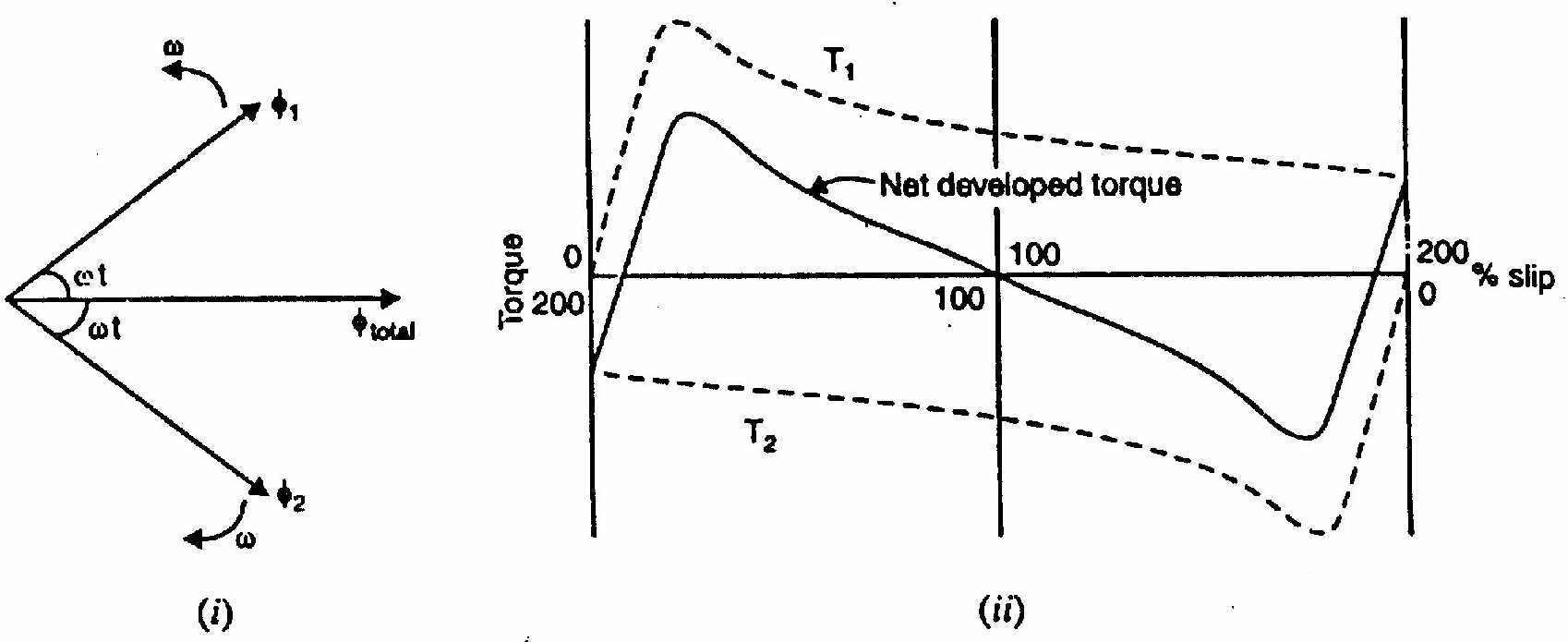
(a) Explain the double-field revolving theory of single-phase IM. [04]
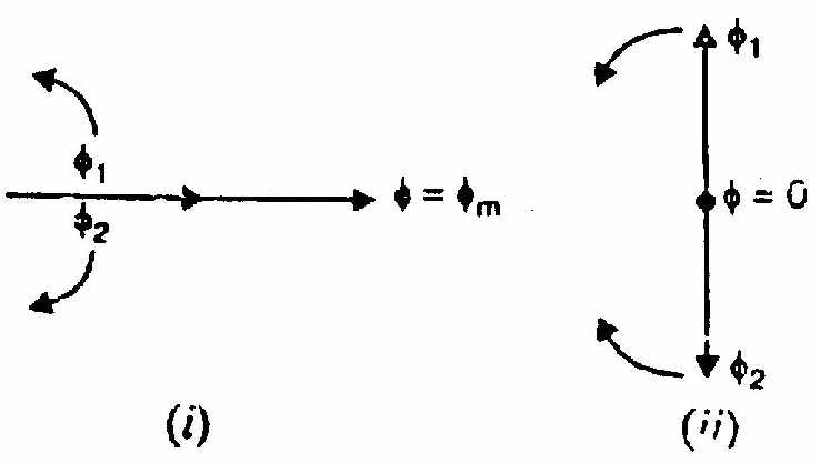
A single-phase stator current i=Imsinωt creates a pulsating flux: Φ=Φmsinωt
Decomposition into two rotating fields:
Using the trigonometric identity: Φmsinωt=2Φmcos(θ−ωt)+2Φmcos(θ+ωt)
At any angle θ, the pulsating field equals:
- Forward field (Φf): Magnitude Φm/2, rotates in the +ve direction at +ω rad/s.
- Backward field (Φb): Magnitude Φm/2, rotates in the −ve direction at −ω rad/s.
At standstill (N=0):
- Slip for forward field: sf=1
- Slip for backward field: sb=1
- Forward torque Tf = backward torque Tb
- Net torque = 0. No self-starting.
At speed N (given a push forward):
- sf=(Ns−N)/Ns=s (small, < 1)
- sb=(Ns+N)/Ns=(2−s) (close to 2, large)
- Tf>Tb (forward torque dominates)
- Motor continues to accelerate and maintains running.
(b) How does a capacitor-start-and-run single-phase IM operate? [04]
A capacitor-start-and-run (or two-value capacitor) motor has:
- Main winding (M): always connected to supply.
- Auxiliary winding (A): permanently connected, with two capacitors:
- Starting capacitor Cst (large value): in circuit during starting only.
- Running capacitor Crun (small value): remains in circuit during running.
Starting operation: Cst (in parallel with Crun) provides large phase advance. The combined capacitance gives nearly 90° phase split between Im and Ia. High starting torque (150–300% of FL torque). Better than a simple capacitor-start motor.
Running operation: After reaching ~75% of Ns, a centrifugal switch opens and disconnects Cst. The motor runs with Crun in circuit. Crun is optimized for running conditions: it maintains better efficiency, power factor, and quieter operation than using no capacitor or the larger Cst.
Advantages: High starting torque + good running performance. Quieter than capacitor-start (auxiliary winding stays on). Better power factor than split-phase.
(c) 250W, 230V, 50 Hz capacitor-start motor. Main winding: Zm=(4.5+j3.7)Ω. Auxiliary winding: Za=(9.5+j3.5)Ω. Find starting capacitor for quadrature currents. [04]
For quadrature currents: Im and Ia must be 90° apart in time.
Main winding angle: ϕm=tan−1(4.53.7)=tan−1(0.822)=39.43° lagging
For Ia to be 90° ahead of Im: Ia must lead voltage by (90°−39.43°)=50.57°.
So the auxiliary + capacitor circuit must have total angle = +50.57° leading.
Auxiliary winding without capacitor: ϕa=tan−1(3.5/9.5)=20.22° lagging.
With capacitor in series, net reactance: Xnet=XC−Xa=XC−3.5
For leading angle of 50.57°: tan(50.57°)=9.5XC−3.5=1.213
XC−3.5=1.213×9.5=11.52
XC=11.52+3.5=15.02Ω
C=2πfXC1=2π×50×15.021=47221=211.8μF
Question 8
(a) Define synchronous watt with an example. [03]
Synchronous watt: A unit of torque used in induction motor calculations. One synchronous watt is the torque that develops one watt of power at synchronous speed.
T (in synchronous watts)=Pg (in watts)
Relationship: T=ωsPg=2πNs/60Pg N-m
So if Pg=1000 W (1 synchronous watt) and Ns=1500 rpm: T=2π×1500/601000=157.081000=6.37 N-m
Example: A motor has air-gap power Pg=5000 W. If synchronous speed is 1000 rpm (ωs=104.7 rad/s): T=104.75000=47.75 N-m
Expressing the torque as 5000 synchronous watts captures both the power and speed dependence in one quantity.
(b) What does vector group of a transformer indicate? What does "Dyn5" represent? [03]
Vector group: A standardized notation that tells you:
- The connection of the primary winding (uppercase letter: Y, D, or Z).
- The connection of the secondary winding (lowercase letter: y, d, or z).
- Whether a neutral is available (letter n).
- The phase displacement between primary and secondary voltages (clock notation: number × 30°).
"Dyn5" means:
- D → Primary winding connected in Delta (Δ)
- y → Secondary winding connected in Star (Y)
- n → Neutral conductor available on the secondary side
- 5 → Phase displacement = 5 × 30° = 150° (secondary voltage lags primary voltage by 150°)
In clock notation: 12 = 0°, 1 = 30°, 5 = 150°. So Dyn5 means the secondary star voltage phasor points to "5 o'clock" relative to the primary delta voltage phasor at "12 o'clock."
(c) Circle diagram: 3-φ, 14.92 kW, 400V, 6-pole IM. No-load: 400V, 11A, pf = 0.2. SC: 100V, 25A, pf = 0.4. Rotor Cu loss at standstill = half total Cu loss. Find from diagram: (i) line current, slip, efficiency, pf at full load; (ii) max torque. [06]
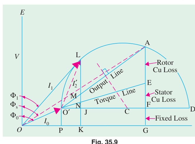
No-load data: I0=11 A, cosϕ0=0.2, ϕ0=78.46°
I0x=11×0.2=2.2 A, I0y=11×sin(78.46°)=11×0.9798=10.78 A
Short-circuit data (referred to full voltage 400V): Isc=25×100400=100 A cosϕsc=0.4, ϕsc=66.42° Iscx=100×0.4=40 A, Iscy=100×0.917=91.65 A
Circle diagram construction:
- Plot no-load point O′ at (I0x,I0y)=(2.2,10.78) A.
- Plot short-circuit point S at (Iscx,Iscy)=(40,91.65) A.
- Draw the circle through O′ and S.
- The power base line is horizontal (active component axis).
- Since rotor Cu loss = stator Cu loss at standstill: the rotor Cu line divides the SC intercept equally (at 50%).
At rated output 14.92 kW:
Input power at rated output (from circle diagram):
Ns=6120×50=1000 rpm
Scale: power scale depends on voltage scale. Using 3×400=692.8 V per unit current.
Power per amp of active component =3×400=692.8 W/A.
For 14.92 kW output, find the point on the circle where the vertical height above the output line equals the output power.
(i) From circle diagram (estimated):
- Full load line current: ≈ 30 A
- Full load slip: ≈ 5%
- Full load efficiency: ≈ 84%
- Full load power factor: ≈ 0.76 lagging
(ii) Maximum torque: Maximum torque corresponds to the longest vertical distance from the circle to the torque line (line from O′ to the point where rotor Cu loss line meets the base line).
Tmax in synchronous watts ≈ read from circle diagram.
Source: PrevYearQuestions/2021.md