PrevYearQuestions/2024.md
7.4 KB · commit d2f3b6e
← 2023 Exam Paper | 🏠 Index | (end)
Rajshahi University of Engineering & Technology
Department of Electrical & Computer Engineering
B.Sc. Engineering 2nd Year Even Semester Examination, 2024
Course No: ECE 2207
Course Title: Electrical Machine - I
Marks: 60
Time: 03 Hours
N.B.
- Answer SIX questions taking any THREE from each section.
- Figures in the margin indicate full marks.
- Use separate answer script for each section.
SECTION - A
Question 1
(a) Enlist some practical applications of transformer. [Marks: 02, CO: 1]
(b) When a power transformer is excited as a manner shown in following figure, then describe the induced voltage phenomena — [Marks: 04, CO: 2]
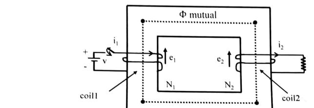
(c) A 2,200/200 — V transformer draws a no-load primary current of 0.6A and absorbs 400W. Find the magnetizing and iron loss currents.
Now, consider a 2,200/250 — V transformer takes 0.5A at a p.f. of 0.3 on open circuit. Find magnetizing and working components of no-load primary current. [Marks: 04, CO: 2]
Question 2
(a) "The magnetizing current of power transformer is not fully sinusoidal" — justify it. [Marks: 02, CO: 1]
(b) Draw and explain the phasor diagram of a power transformer, when the transformer is loaded with "R-L" load. [Marks: 04, CO: 1]
(c) A 50 KVA, 2200/110 V transformer when tested gave the following results: [Marks: 04, CO: 2]
- O.C. test (L. V. side): 400W, 10A, 110V
- S. C. test (H. V. side): 808W, 20.5A, 90V
Compute all the parameters of the equivalent circuit referred to the H. V. side and draw the resultant circuit.
Question 3
(a) Define voltage regulation of transformer. [Marks: 02, CO: 1]
(b) Explain with the help of vector diagram, how three 1-φ transformers can be used to design a 3-φ transformer. [Marks: 04, CO: 2]
(c) In no-load test of single-phase transformer, the following test data were obtained: [Marks: 04, CO: 2]
- Resistance of primary winding =0.6 Ω;
- Primary voltage: 220 V;
- Secondary voltage: 110 V;
- Primary current: 0.5 A;
- Power input: 30 W
Find the followings:
- i) The turn ratio
- ii) The magnetizing component of no-load current
- iii) Its working (or loss) component
- iv) The iron loss
Question 4
(a) In performing the short circuit test of a transformers, HV side is usually short circuited — explain it. [Marks: 02, CO: 2]
(b) Is it possible to maintain 3-φ power supply when one phase of a 3-φ transformer is burned out? If 'Yes', justify the answer. If 'Not', then also justify your answer. [Marks: 04, CO: 1]
(c) Two T-connected transformers are used to supply a 440 V, 33KVA balanced load from a balanced 3-φ supply of 3300 V. Calculate — [Marks: 04, CO: 2]
- i) voltage and current rating of each coil.
- ii) KVA rating of the main and teaser transformer.
SECTION - B
Question 5
(a) Explain how a rotating field is produced when a balanced 3-φ induction motor is connected to a balanced 3-φ supply. [Marks: 03, CO: 3]
(b) Define slip. Prove that an induction motor cannot run at synchronous speed. [Marks: 03, CO: 3]
(c) A 12 pole, 3-φ alternator driven at a speed of 500 r.p.m supplies power to an 8-pole, 3-φ induction motor. If the slip of the motor, at full load is 3%, calculate the full-load speed of the motor. [Marks: 04, CO: 3]
Question 6
(a) Define starting and running torque of an induction motor (IM). [Marks: 02, CO: 1]
(b) Following step by step process, draw and describe the vector diagram of a 1-φ IM. [Marks: 04, CO: 1]
(c) A 3-φ, slip-ring IM with star-connected rotor has an induced emf of 120 volts between slip-rings at standstill with normal voltage applied to the stator. The rotor winding has a resistance per phase of 0.3 Ω and stand-still leakage reactance per phase of 1.5 Ω. Determine — [Marks: 04, CO: 2]
- i) Rotor current/phase when running short circuited with 4% slip and
- ii) The slip and rotor current per phase when the rotor is developing maximum torque.
Question 7
(a) Enlist the test's name used for determining circuit model parameters of an IM. [Marks: 02, CO: 1]
(b) Prove that, [Marks: 04, CO: 1] Tmax=2πNs32X2E22 N-m Variables having their usual meanings.
(c) A 50 Hz, 8 pole induction motor has F.L. slip of 4%. The rotor resistance/phase =0.01 Ω and stand still reactance/phase =0.1 Ω. Find the ratio of maximum to full-load torque and the speed at which the maximum torque occurs. [Marks: 04, CO: 3]
Question 8
(a) Draw the torque ~ slip of 3-φ induction machine. [Marks: 02, CO: 1]
(b) Describe the process following which an IM can be operated as IG. [Marks: 04, CO: 2]
(c) A 440V, 4-pole, 1470 rpm, 30-kW, 3-φ IM is to be used as IG, the rated current of the motor is 40A and full-load power factor is 85%. Now, calculate — [Marks: 04, CO: 2]
- i) Capacitance required per phase if capacitors are connected in delta.
- ii) Speed of the driving engine for generating a frequency of 50Hz.
← 2023 Exam Paper | 🏠 Index | (end)