boss_notes/T-17b_Blocked_Rotor_Test.md
5.4 KB · commit d2f3b6e
← T-17a: No-Load Test | 🏠 Index | T-18: Circle Diagram →
T-17b: Blocked Rotor Test
Section: B | Priority: 🟠 HIGH | Exam Frequency: 4/7 years Sources: Theraja Ch-35 (Art. 35.6-35.8), VK Mehta Ch-8, Slides L-05
Why This Topic Matters
The blocked rotor test is always tested together with the no-load test. The pair appeared in 4 out of 7 papers. The blocked rotor test determines the series impedance (R01, X01) of the equivalent circuit. A standalone SC test numerical (given Vsc, Isc, Psc, find R2′, X1, X2′) appeared in 2023 Q7(b) for 4 marks.
📝 Key Definitions
Blocked Rotor Test (Locked Rotor Test): "The rotor is held stationary (locked) so that it cannot rotate. A reduced voltage (10-15% of rated) is applied to the stator so that rated full-load current flows. Since the voltage is low, core losses are negligible and the input power is essentially the full-load copper loss." — Theraja, Art. 35.6
Test Setup and Procedure
- Lock the rotor mechanically so it cannot rotate (s=1).
- Apply reduced voltage to the stator until rated full-load current flows.
- Measure: line voltage Vsc, line current Isc, total 3-phase input power Psc.
What happens at blocked rotor:
- s=1, so R2/s=R2 (small value). The rotor branch draws heavy current.
- At low voltage (10-15% of rated), the shunt branch current is negligible.
- All input power is copper loss: Psc=PCu,s+PCu,r.
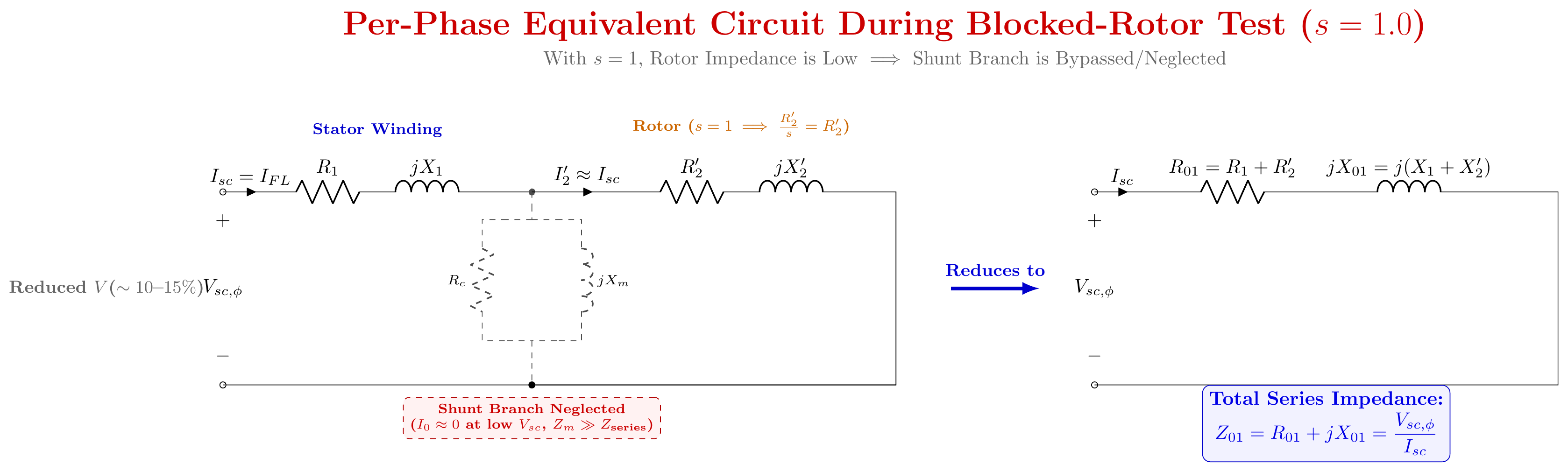
Parameters from Blocked Rotor Test
Equivalent impedance referred to stator (per phase):
Z01=IscVsc/3(star connection)
R01=3Isc2Psc
X01=Z012−R012
Separating stator and rotor parameters:
R2′=R01−R1
where R1 is from the DC resistance test.
X1=X2′=2X01
(Assuming equal leakage reactances on stator and rotor sides.)
DC Resistance Test (for R1)
Apply DC voltage between two stator terminals. Measure VDC and IDC.
RDC=VDC/IDC
For star connection: R1=RDC/2 (two phases in series)
For delta connection: R1=1.5×RDC (parallel-series combination)
Worked Example (PYQ 2023)
2023 Q7(b): Star-connected IM, SC test: V=75 V, I=38 A, P=4 kW. R1=0.5Ω/phase. Find R2′, X1, X2′.
Per-phase voltage: Vsc,ϕ=75/3=43.30 V
Z01=3843.30=1.140Ω
R01=3×3824000=43324000=0.923Ω
X01=1.1402−0.9232=1.300−0.852=0.448=0.669Ω
R2′=R01−R1=0.923−0.5=0.423Ω
X1=X2′=X01/2=0.669/2=0.335Ω
🏆 Golden Questions (Past Exam Archive)
🎯 Q1: Explain the no-load and blocked rotor tests. Determine equivalent circuit parameters.
Appeared: 2023 Q7(a), 2024 Q7(a) — (9 marks)
Full Answer:
See T-17a: No-Load Test for the no-load test portion.
Blocked-Rotor Test:
Rotor mechanically locked (s=1). Reduced voltage (10-15% of rated) applied until rated current flows. At low voltage, core loss is negligible. Input power = full-load copper loss.
Measurements: Vsc (line voltage), Isc (line current), Psc (3-phase power).
Parameters:
Z01=IscVsc/3,R01=3Isc2Psc,X01=Z012−R012
Split: R2′=R01−R1, and X1=X2′=X01/2.
DC Test for R1: Apply DC between two stator terminals. Star: R1=RDC/2. Delta: R1=1.5RDC.
🎯 Q2: SC test numerical: V=75 V, I=38 A, P=4 kW, R1=0.5Ω. Find R2′, X1, X2′.
Appeared: 2023 Q7(b) — (4 marks)
Full Answer:
See Worked Example above. Results: R2′=0.423Ω, X1=X2′=0.335Ω.
Exam Variants
| Year | Question | Marks | Type |
|---|---|---|---|
| 2019 Q7(a) | Describe blocked rotor test | 4 | Theory |
| 2023 Q7(a) | Explain NL + BR tests | 9 | Theory + formulas |
| 2023 Q7(b) | SC test numerical | 4 | Numerical |
| 2024 Q7(a) | NL + BR tests + parameters | 9 | Theory + formulas |
⚡ Exam Tips & Common Mistakes
- Don't forget 3. For star connection: Vϕ=VL/3. For delta: Vϕ=VL.
- R01 includes BOTH stator and rotor resistance. R2′=R01−R1.
- The assumption X1=X2′ is standard unless told otherwise. State it explicitly.
- Blocked rotor test is analogous to SC test of transformer. Same formulas, same logic.
- Power formula uses LINE current: R01=Psc/(3Isc2) where Isc is the LINE current (which equals phase current for star).
🔗 Related Topics
- T-17a: No-Load Test — Always paired
- T-14: IM Equivalent Circuit — The circuit being determined
- T-18: Circle Diagram — Uses BR test data as input