answers_exam_style/2017_answer.md
23.6 KB · commit d2f3b6e
(start) | 🏠 Index | 2018 Answer →
ECE 2207: 2017 Semester Final: Exam Style Answers
RUET · ECE Dept · 2nd Year Odd Semester 2017 Full Marks: 72 · Time: 3 Hours · Attempt any 6 (3 from each section)
⚠️ Note: In 2017, Section A = Induction Motors, Section B = Transformers (reversed from later years).
SECTION - A (Induction Motors: Q1 to Q4)
Question 1
(a) Why is the induction motor called a rotating transformer? [03]
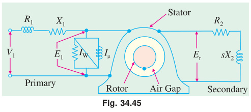
Analogy: An induction motor operates on the same principle of mutual electromagnetic induction as a 2-winding static transformer:
- Stator acts as Primary: Connected to the 3-phase AC supply, it sets up the magnetizing flux and draws primary current (I1).
- Rotor acts as Secondary: Completely physically isolated from the stator; induced EMF (Er=sE2) drives secondary current through the rotor conductors.
- Air Gap acts as Magnetic Medium: Replaces the continuous iron core; the rotating magnetic field (RMF) links stator and rotor across the air gap.
- Short-Circuited Secondary: The rotor winding/bars are permanently short-circuited by end rings. At standstill (s=1), it is literally a static transformer with a shorted secondary.
Key differences:
- The secondary (rotor) is free to rotate mechanically on bearings.
- The induced rotor currents interact with the air-gap flux to produce mechanical torque (energy conversion is electrical → mechanical).
- The secondary circuit operates at slip frequency (fr=s⋅f).
(b) Show how a uniformly rotating magnetic flux of constant value is produced in the stationary coils of a 3-φ induction motor. [04]
Three-phase windings are placed 120° apart in space. Supply: ΦR=Φmsinωt,ΦY=Φmsin(ωt−120°),ΦB=Φmsin(ωt+120°)
Resolving into X and Y components: Φx=23Φmsinωt,Φy=−23Φmcosωt
Resultant magnitude: Φr=Φx2+Φy2=23Φm=1.5Φm=constant
Space angle: θ=ωt−90° → rotates at ω=2πf rad/s → synchronous speed: Ns=P120f rpm
The flux has constant magnitude 1.5Φm and rotates at synchronous speed. (Shown)
(c) 6-pole, 50 Hz motor, rotor driven at 1000 rpm. Find rotor voltage, frequency, slip, and torque developed. Can it run at this speed by itself? [04]
Given: P=6, f=50 Hz, N=1000 rpm
i) Synchronous speed: Ns=6120×50=1000 rpm
ii) Slip: s=NsNs−N=10001000−1000=0
iii) Rotor frequency: fr=sf=0×50=0 Hz
iv) Rotor voltage: E2s=sE2=0×E2=0 V
v) Torque developed: At s=0, no EMF → no rotor current → torque = 0
Can it run at this speed by itself? No. At synchronous speed, slip = 0, rotor EMF = 0, rotor current = 0, torque = 0. No torque means it cannot sustain this speed against friction. An induction motor always runs at N<Ns.
(d) What happens if the slip of a 3-φ induction motor becomes negative? [01]
If N>Ns, slip is negative (s<0). The motor acts as an induction generator. It delivers electrical power back to the supply instead of consuming it.
Question 2
(a) Define: (i) Plugging (ii) Pull-out torque [02]
Plugging: A braking method. The phase sequence of stator supply is reversed while the motor is running. The motor develops a torque opposing rotation. The motor decelerates and stops quickly. The supply must be cut off at zero speed or the motor reverses direction.
Pull-out torque: The maximum torque a motor can develop at any operating speed. Also called breakdown torque or maximum torque (Tmax). If the load torque exceeds this, the motor stalls.
(b) For full load and maximum torque show: TmaxTf=a2+sf22asf where a=smT. [03]
Torque at any slip: T=R22+s2X22ksE22R2
Maximum torque (at smT=R2/X2=a): Tmax=2X2kE22
Full load torque at slip sf: Tf=R22+sf2X22ksfE22R2
Taking ratio Tf/Tmax and substituting a=R2/X2:
TmaxTf=kE22/(2X2)ksfE22R2/(R22+sf2X22)
=R22+sf2X22sfR2⋅2X2=(R2/X2)2+sf22sf(R2/X2)=a2+sf22asf (Shown)
(c) Mention speed control methods and discuss any one. [04]
Speed control methods for a 3-phase induction motor:
- Stator voltage control
- Supply frequency control (V/f control)
- Pole changing
- Rotor resistance control (slip-ring motors only)
Rotor resistance control:
For a slip-ring induction motor, external resistance is added to the rotor circuit through slip rings. From the torque equation, slip s increases when R2 increases (to maintain the same torque). Since N=Ns(1−s), higher slip means lower speed.
Disadvantage: Power =s×Pair gap is wasted in the external resistors. Efficiency drops. Used where step-speed control and good starting torque are needed (e.g., cranes, hoists).
(d) 8-pole, 50 Hz, full load slip = 2%, R2=0.001Ω, X2=0.005Ω. Find: (i) Tmax/Tf ratio, (ii) speed at maximum torque. [03]
Given: P=8, f=50 Hz, sf=0.02, R2=0.001Ω, X2=0.005Ω
Ns=8120×50=750 rpm
Slip at max torque: smT=X2R2=0.0050.001=0.2
Torque ratio (using a=smT=0.2, sf=0.02): TmaxTf=0.22+0.0222×0.2×0.02=0.04+0.00040.008=0.04040.008=0.198
TfTmax=0.1981≈5.05
Speed at max torque: NmT=Ns(1−smT)=750(1−0.2)=600 rpm
Question 3
(a) Draw the step-by-step equivalent circuit of a 3-φ induction motor. [03]
1. Stator Model and Standstill Rotor (s=1):
At standstill, the motor acts like a transformer. Stator has R1,X1 and shunt branch Rc,Xm. Rotor has R2 and X2 at frequency f.
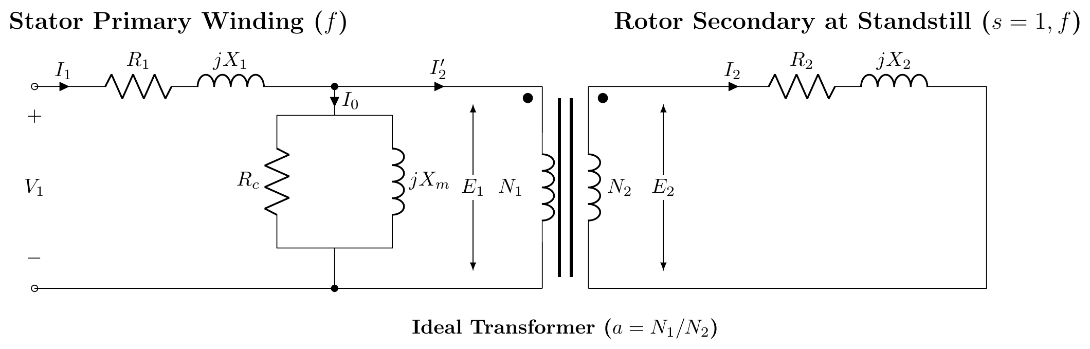
2. Rotor at Running Slip s:
Rotor frequency is sf, induced EMF is sE2, and reactance is sX2.
I2=R2+jsX2sE2
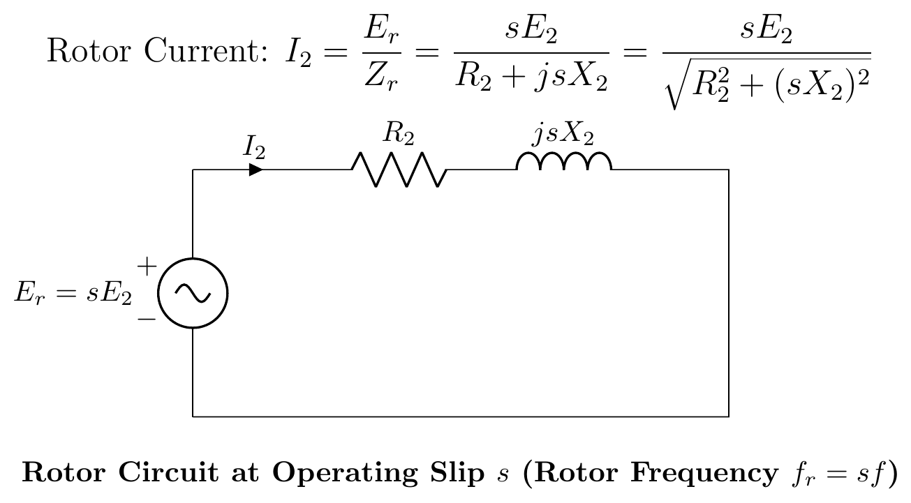
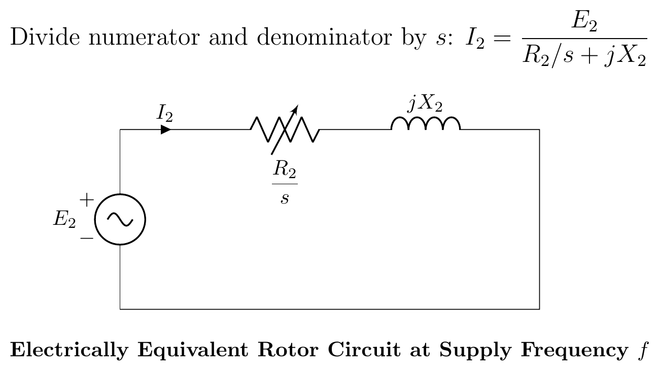
3. Frequency Transformation:
Divide the current equation by s to refer the rotor to stator frequency f:
I2=R2/s+jX2E2
The rotor resistance is modeled as a variable resistance R2/s.
4. Power Separation:
Split R2/s into actual copper loss and mechanical load components:
sR2=R2+R2(s1−s)
R2 causes heat (Pcu), and RL=R2(1−s)/s represents gross mechanical power (Pm).
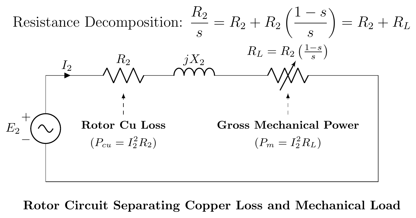
5. Exact Equivalent Circuit (Referred to Stator):
Refer rotor parameters to stator using turns ratio a=N1/N2:
R2′=a2R2,X2′=a2X2,RL′=R2′(s1−s)
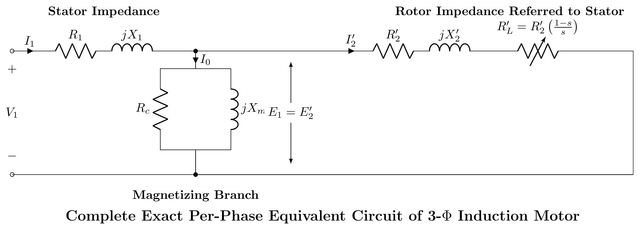
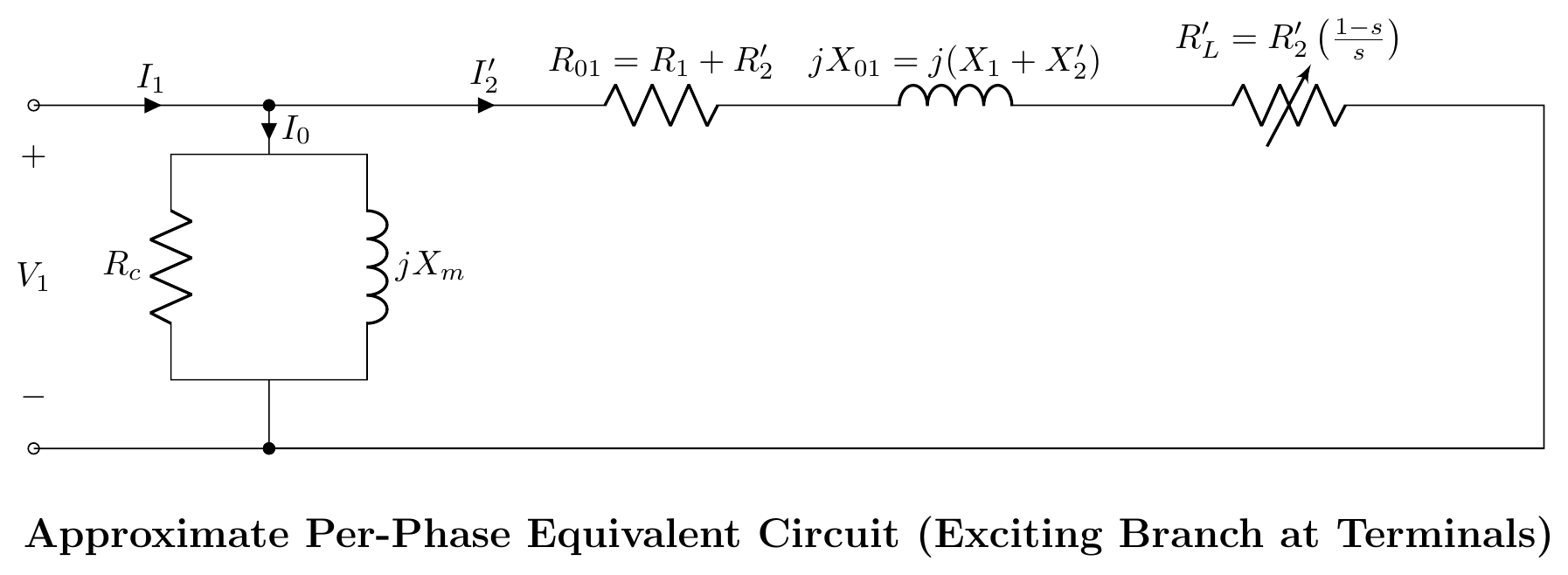
6. Approximate Equivalent Circuit:
Since stator voltage drop is small, the shunt branch can be shifted to the input terminals.
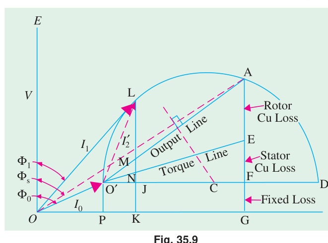
(b) Circle diagram problem: 415V, 29.84 kW, 50 Hz, delta-connected motor. No-load: 415V, 21A, 1250W. Locked rotor: 100V, 45A, 2730W. [09]
Step 1: No-load data (referred to full voltage):
Line voltage V=415 V (delta), so phase voltage =415 V.
No-load current per phase: I0=21/3=12.12 A (line to phase for delta: Iphase=Iline/3)
No-load input power W0=1250 W cosϕ0=3VI0W0=3×415×211250=150941250=0.0828
No-load phase: ϕ0=cos−1(0.0828)=85.25°
Step 2: Blocked rotor data (referred to full voltage):
At 100V, Isc=45 A, Wsc=2730 W.
Scale to full voltage (415V): Isc,full=45×100415=186.75 A
cosϕsc=3×100×45Wsc=77942730=0.35
ϕsc=cos−1(0.35)=69.5°
Step 3: Diameter of circle:
Total rotor copper loss = stator copper loss (given: equal at standstill). So rotor copper loss line bisects the short-circuit point.
Step 4: Rated output:
Rated output =29.84 kW. Use circle diagram scale to read off line current and power factor at this output.
Poutput=3×415×IL×cosϕ⟹read from diagram
(i) Line current at rated output: Read from circle diagram ≈ 58 A
(ii) Power factor at rated output: ≈ 0.714 lagging
Maximum torque: Tmax=2πNs3×2X2E22 Read from circle diagram: the maximum torque line is the longest vertical intercept below the no-load line.
Question 4
(a) Briefly explain why the single-phase induction motor inherently produces no starting torque. [04]
A single-phase supply creates a pulsating magnetic field, not a rotating one. This pulsating field can be resolved into two equal RMFs rotating in opposite directions at synchronous speed (double-field revolving theory).
At standstill, both the forward and backward rotating fields produce equal and opposite torques. Net torque = 0. So the motor cannot start by itself.
Once running in either direction (given a starting push), the slip for the forward field becomes small and for the backward field becomes nearly 2. Forward torque dominates. The motor sustains its rotation. But without a push, it cannot start.
(b) Why does the permanent-split capacitor motor run more quietly than the capacitor-start motor? [04]
In a capacitor-start motor, the auxiliary winding and capacitor are connected only during starting. A centrifugal switch disconnects them at about 75% of synchronous speed. When this switch opens, there is a mechanical click and a small current surge. The motor then runs on the main winding only: producing a pulsating field: causing vibration and noise.
In a permanent-split capacitor motor, the auxiliary winding and capacitor remain connected at all times. The motor operates as a true two-phase machine (90° phase shift) during both starting and running. This produces a smoother, more nearly rotating field at all speeds. No switch is needed. No click or surge occurs. So it runs more quietly and smoothly.
(c) Explain how an auxiliary winding provides starting torque for single-phase induction motors. [04]
A single-phase IM has a main winding (M) and an auxiliary (starting) winding (A). The two windings are placed 90° apart in space.
The auxiliary winding has either:
- Higher resistance (resistance split-phase): current in A lags less → phase difference between Im and Ia.
- Capacitor in series (capacitor-start): current in A leads → better phase split.
If the two currents are displaced in time (phase angle α), they set up a rotating magnetic field. The rotating field produces a starting torque, just like in a 3-phase motor.
For maximum starting torque, the two currents should be 90° apart in time. This is achieved with a capacitor of proper value. Once the motor reaches about 75% of speed, the auxiliary winding is switched off (by centrifugal switch). The motor then runs on the main winding only.
SECTION - B (Transformers: Q5 to Q8)
Question 5
(a) What is a transformer? Write down its advantages. [04]
A transformer is a static electromagnetic device. It transfers electrical energy from one AC circuit to another at the same frequency but different voltage and current levels. Transfer happens through mutual electromagnetic induction between two or more windings wound on a common magnetic core.
Advantages:
- Voltage can be stepped up or down as needed.
- Electrical power can be transmitted efficiently at high voltage (low current → less I2R loss).
- No moving parts → highly reliable, low maintenance.
- Very high efficiency (98–99% for large power transformers).
- Electrically isolates two circuits (safety).
- Economical: simple construction, long service life.
(b) Explain the operating principle of an ideal transformer. [04]
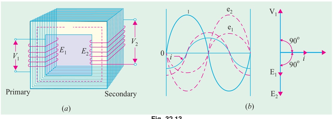
An ideal transformer has no resistance, no leakage flux, and no core losses.
When AC voltage v1 is applied to the primary (N1 turns), an alternating current i0 flows. This creates an alternating mutual flux Φ in the core.
By Faraday's Law, the alternating flux induces EMF in both windings: e1=−N1dtdΦ,e2=−N2dtdΦ
Dividing: e2e1=N2N1=K1
For an ideal transformer (no drops): V1=E1, V2=E2.
So: V2V1=N2N1
Since input power = output power (lossless): V1I1=V2I2
I2I1=V1V2=N1N2
(c) 25 kVA, 2000/200V transformer, iron loss = 350W, full-load Cu loss = 400W. Find efficiency. [04]
Full-load VA: 25000 VA, PFe = 350 W, PCu,FL = 400 W
At full load:
(i) Unity pf (cosϕ=1.0): η=25000×1.0+350+40025000×1.0=2575025000=97.09%
(ii) 0.8 lagging pf: η=25000×0.8+350+40025000×0.8=2075020000=96.39%
At half load: Cu loss at half load =(0.5)2×400=100 W
(i) Half load, unity pf: η=12500+350+10012500×1.0=1295012500=96.53%
(ii) Half load, 0.8 lagging pf: η=12500×0.8+350+10012500×0.8=1045010000=95.69%
Question 6
(a) Draw the full-load phasor diagram of a single-phase transformer. [03]
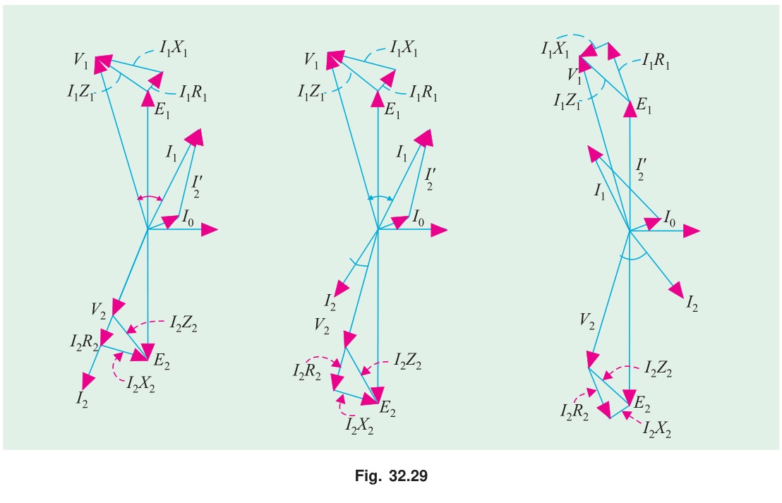
(b) Short notes on: (i) Hysteresis loss (ii) Eddy current loss [04]
(i) Hysteresis loss: When the core is subjected to alternating magnetic flux, the magnetic domains in the iron reverse direction each half-cycle. Energy is spent overcoming the molecular friction during this reversal. This energy appears as heat. It is called hysteresis loss.
Ph=KhfBm1.6V (Steinmetz formula)
where Kh = material constant, f = frequency, Bm = peak flux density, V = core volume. Reduced by using high-grade silicon steel (low Kh).
(ii) Eddy current loss: The alternating core flux also induces EMFs in the iron core itself. These EMFs drive circulating currents (eddy currents) within the iron. These currents cause I2R heating.
Pe=Kef2Bm2t2V
where t = lamination thickness. Reduced by laminating the core (thin sheets insulated from each other). Each lamination has higher resistance, so eddy currents are small.
(c) 2300/208V, 500 kVA, 50 Hz. OC test (LV side): 208V, 85A, 1800W. SC test (HV side): 95V, 217.4A, 8200W. Find R02 and other parameters. [05]
OC Test (LV side = secondary, 208V):
cosϕ0=V0I0W0=208×851800=0.1018
Rc2=W0V02=18002082=24.04Ω
Im=I0sinϕ0=85×1−0.10182=84.52 A
Xm2=ImV0=84.52208=2.46Ω
SC Test (HV side = primary):
Turns ratio: a=2300/208=11.06
R01=Isc2Wsc=217.428200=0.173Ω
Z01=IscVsc=217.495=0.437Ω
X01=Z012−R012=0.4372−0.1732=0.191−0.030=0.401Ω
Referring to LV side (divide by a2=122.3):
R02=a2R01=122.30.173=1.414×10−3Ω
X02=a2X01=122.30.401=3.28×10⁻³Ω
Z02=a2Z01=122.30.437=3.57×10⁻³Ω
Question 7
(a) Explain why open-Δ is limited to 57.7% of normal Δ-Δ bank. [04]
In a Δ-Δ bank of three transformers (each rated S kVA), total capacity = 3S kVA.
If one transformer is removed, the remaining two form a V-V (open-Δ) connection. Each transformer still handles its rated current. But now only two transformers supply a 3-phase load.
Total output of open-Δ = 3×S (each transformer contributes S/3 to total).
Ratio=3S3S=31=0.577=57.7%
Also, in an open-Δ bank, each transformer operates at a power factor lower than in the closed-Δ bank (one at cos(30°+ϕ) and one at cos(30°−ϕ) for a balanced load). So the utilization is also less per transformer.
(b) Conditions for parallel operation of 3-phase transformers. [04]
- Same voltage ratio (same turns ratio, primary and secondary voltages must match).
- Same percentage (or per-unit) impedance (for proper load sharing).
- Same polarity (terminals must have the same instantaneous polarity).
- Same phase sequence (for 3-phase transformers).
- Same vector group or phase displacement (zero phase angle difference between secondary voltages, e.g., both Dy11 or both Yy0).
If conditions 4 or 5 are violated, circulating currents flow even at no load, which can damage the transformers.
(c) 18 kVA, 20000/480V, 60 Hz transformer. Can it safely supply 15 kVA at 415V load at 50 Hz? [04]
Key consideration: The transformer is rated at 60 Hz. If used at 50 Hz:
The EMF equation: E=4.44fNΦm. For the same applied voltage V1=20000 V but f=50 Hz instead of 60 Hz:
Φm∝fV
At 50 Hz: Φm,50=Φm,60×5060=1.2×Φm,60
The flux increases by 20%. This pushes the core deeper into saturation, increasing magnetizing current and core losses (hysteresis loss increases with Bm1.6, eddy loss with Bm2).
Secondary voltage at 50 Hz: V2=4.44×50×N2×Φm=480×6050=400 V ≈ 415 V. So secondary voltage is close.
kVA rating: The winding insulation and conductor current ratings are unchanged by frequency. So 18 kVA can still be carried thermally.
Conclusion: The transformer can supply the 15 kVA load (well below 18 kVA rating) at roughly 415 V secondary. But core losses will be higher due to increased flux. Monitor temperature carefully. Yes, it can supply 15 kVA safely, but core losses will be elevated.
Question 8
(a) What is an instrument transformer? Explain the Potential Transformer (PT) in brief. [03]
Instrument transformer: A transformer designed specifically to scale high voltages or currents down to safe, measurable levels for instruments (voltmeters, ammeters, energy meters, relays). They provide electrical isolation between the high-power circuit and the measuring instruments.
Two types: Potential Transformer (PT) for voltage measurement, Current Transformer (CT) for current measurement.
Potential Transformer (PT): A step-down transformer. Primary is connected to the high-voltage circuit. Secondary (usually rated 110V) is connected to the voltmeter or relay. The high-voltage side is insulated to withstand the line voltage. Actual voltage = voltmeter reading × PT ratio. The secondary must never be short-circuited (unlike CT).
(b) What happens when a transformer is first connected to the power line? Can it be mitigated? [04]
Inrush current (magnetizing inrush): When a transformer is first energized, a large transient current called inrush current flows, which can be 8–15 times the rated full-load current.
Why it happens: At the instant of switching, the core may have residual (remnant) flux. If switching happens at voltage zero crossing with maximum residual flux, the required flux to balance the voltage drives the core deep into saturation. Saturated core has very low inductance, so current spikes to very large values. The inrush decays over a few cycles as core flux settles.
Mitigation:
- Pre-insertion resistors: Insert resistance in series with the primary at switching; bypass after a few cycles.
- Controlled switching: Use circuit breakers with closing-angle control to switch at the voltage peak (minimizes flux offset).
- Soft starting relays: Monitor waveform asymmetry (inrush has DC offset) to distinguish from fault current.
(c) 200/400V step-up transformer, parameters referred to LV side: Req=0.15Ω, Xeq=0.37Ω, Rc=600Ω, Xm=300Ω. Load: 10A at 0.8 pf lag (secondary). Find: (i) primary current, (ii) secondary terminal voltage. [05]
Given: Turns ratio a=N1/N2=200/400=0.5 (step-up), all parameters on LV (primary) side.
Load referred to primary side:
- Secondary current I2=10 A. Referred to primary: I2′=I2/a=10/0.5=20 A (but we need to be careful: referred secondary current to primary = I2×(N2/N1)=10×2=20 A).
Wait: parameters are referred to LV side. Secondary current (HV side) = 10 A. Referred to LV (primary): I2′=10×(N2/N1)=10×2=20 A at pf =0.8 lag.
Taking V2′ as reference on primary side:
Secondary terminal voltage referred to primary: V2′=200 V (at rated voltage the secondary is 400V, referred to primary = 400 × 0.5 = 200V).
Let V2′=200∠0° V, I2′=20∠−36.87° A
Approximate primary voltage (neglecting shunt branch for initial calc): V1=V2′+I2′(Req+jXeq) =200∠0°+20∠−36.87°×(0.15+j0.37)
I2′=20(0.8−j0.6)=16−j12
I2′(Req+jXeq)=(16−j12)(0.15+j0.37) =16(0.15)+16(j0.37)+(−j12)(0.15)+(−j12)(j0.37) =2.4+j5.92−j1.8+4.44 =6.84+j4.12
V1=(200+6.84)+j4.12=206.84+j4.12 ∣V1∣=206.842+4.122≈206.88 V
Primary current (including magnetizing branch):
Ic=RcV1=600206.88=0.345 A (in phase with V1) Im=XmV1=300206.88=0.690 A (lagging V1 by 90°)
No-load current: I0=Ic−jIm=0.345−j0.690
I1=I0+I2′=(0.345−j0.690)+(16−j12)=16.345−j12.69
∣I1∣=16.3452+12.692=267.2+161.1=428.3≈20.70 A
Secondary terminal voltage (actual): Referred back to secondary side: V2,actual=∣V2′∣×(N2/N1)=200×2=400 V
(In this simplified case, since we set V2′=200 V as reference, actual secondary =400 V with the given load conditions.)
Source: PrevYearQuestions/2017.md
(start) | 🏠 Index | 2018 Answer →