SlidesByMaam/L-05_ECE-2107.md
9.8 KB · commit d2f3b6e
Electrical Machines-I
ECE-2107
Induction Motor-SL4
Fariya Tabassum
Assistant Professor, Dept. of Electrical & Computer Engineering
Rajshahi University of Engineering & Technology, Rajshahi-6204
“So which of the favors of your lord would you deny”.
[Sura Ar-Rahman]
Determining Circuit Model Parameters of Induction Motor
The equivalent circuit of an induction motor is a very useful tool for determining the motor's response to changes in load. The cases where induction motor parameters (R1,R2,X1,X2,XM) are not readily available from the manufacturer they can be approximated from a DC test, no-load test and blocked-rotor test. The tests must be performed under precisely controlled conditions.
No-load Test
The no-load test is used to determine the magnetizing reactance XM and the combined core friction and windage losses. These losses are essentially constant for all load conditions. The power input is measured by two wattmeters, current by an ammeter and voltage by the voltmeter as shown in the following figure.
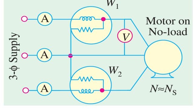
No-load Test
At no-load, the operating speed is very close to synchronous speed; the slip is ≈0, causing the current in the R2/s to be very large. For this reason, the R2/s branch is drawn with dotted lines as shown in the following figure and omitted from the no-load current calculations.
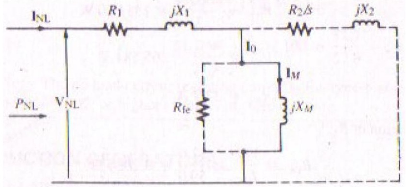
No-load Test
Moreover, since IM≫Ife, Io≈IM, thus the Rfe is also drawn with dotted lines as shown in the figure and omitted from the no-load current calculations. Referring to the approximate equivalent circuit for the no-load test, the apparent input power per phase is
SNL=VNLINL
The reactive power per phase is determined by
SNL=PNL2+QNL2
QNL=SNL2−PNL2
No-load Test
Expressing the reactive power in terms of current and reactance, and solving for the equivalent reactance at no-load
QNL=INL2XNL
Thus
XNL=INL2QNL
For the reduced equivalent circuit it can be written that
XNL=X1+XM
Substituting the value of X1 as determined from the blocked rotor test, permits the determination of XM.
No-load Test
The input power per phase at no load includes the small staror copper loss, core loss and loss due to friction and windage. That is,
PNL=INL2R1+Pcore+Pw,f
Blocked Rotor Test
It is sometimes known as locked-rotor test. In this test the rotor is locked or blocked so that it cannot move. To perform the locked-rotor test, an ac voltage is applied to the stator, and the current flow is adjusted to be approximately full-load value, When the current is full-load value, the voltage, current, and power flowing into the motor are measured. Since, the rotor is not moving, slip=1 and so the rotor resistance R2/s is just equal to R2 (quite a small value). Since R2 and X2 are so small, almost all the input current will flow through them instead of through the much larger magnetizing reactance XM. Therefore the circuit under these conditions looks like a series combination of R1, X1, R2 and X2.
Blocked Rotor Test
After a test voltage and frequency have been set up, the current flow in the motor is quickly adjusted to about the rated value and the input power voltage and current are measured before the rotor can heat up too much. The input power to the motor is given by
Pin=3VTILcosθ
So the locked rotor power factor can be found as
PF=cosθ=3VTILPin
The magnitude of the total impedance in the motor circuit at this time is
∣ZLR∣=3ILVTϕ
Blocked Rotor Test
Again
ZLR=RLR+jXLR′
=∣ZLR∣cosθ+j∣ZLR∣sinθ
The locked rotor resistance RLR is equal to RLR=R1+R2
While the locked rotor reactance XLR′ is equal to XLR′=X1′+X2′
Where X1′ and X2′ are the stator and rotor reactances at the test frequency respectively.
The rotor resistance R2 can now be found as
R2=RLR−R1
Where R1 can be determined from the dc test. The total rotor reactance referred to the stator can also be found. Since the reactance is directly proportional to the frequency, the total equivalent reactance at the normal operating frequency can be found as
XLR=ftestfrated(X1+X2)
DC Test for Stator Resistance
The rotor resistance R2 plays an extremely critical role in the operation of an induction motor. Among other things this resistance determines the shape of the torque-speed curve, determining the speed at which the pullout torque occurs. A standard motor test called the locked-rotor test can be used to determine the total motor circuit resistance. However, this test finds only the total resistance. To find out the rotor resistance R2 accurately, it is necessary to know R1 so that it can be subtracted from the total.
There is a test for R1 independent of R2, X1 and X2. This test is called the DC test. Basically, a DC voltage is applied to the stator windings of an induction motor. Because the current is DC, there is no induced voltage in the rotor circuit and no resulting rotor current flows. Also, the reactance of the motor is zero at direct current. Therefore, the only quantity limiting current flow in the motor is the stator resistance, and that resistance can be determined.
DC Test for Stator Resistance
The purpose of the DC test is to determine R1. This is accomplished by connecting any two stator leads to a variable voltage DC source as shown in the following figure. The DC source is adjusted to provide approximately rated stator current and the resistance between two stator leads is determined from the voltmeter and ammeter readings. Thus
RDC=IDCVDC
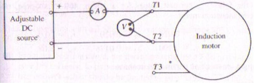
DC Test for Stator Resistance
If the stator is Y connected
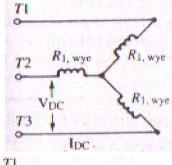
RDC=2R1,wye
R1,wye=2RDC
If the stator is Δ connected
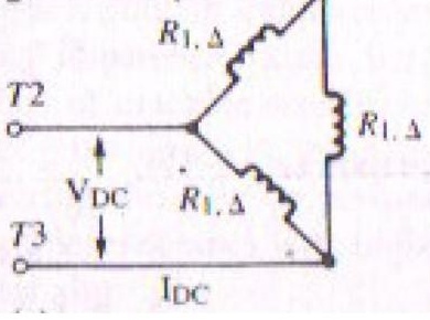
RDC=3R1,ΔR1,Δ2+3R1,ΔR1,Δ2
RDC=32R1,Δ
R1,Δ=1.5RDC
Problems
The following data were obtained from no-load, blocked-rotor, and DC tests of a three-phase, wye-connected, 40-hp, 60-Hz, 460-V, design B induction motor whose rated current is 57.8 A. The blocked-rotor test was made at 15 Hz.
| Blocked Rotor | No-Load | DC |
|---|---|---|
| Vline=36.2 V | Vline=460.0 V | VDC=12.0 V |
| Iline=58.0 A | Iline=32.7 A | IDC=59.0 A |
| P3 phase=2573.4 W | P3 phase=4664.4 W |
(a) Determine R1,X1,R2,X2,XM, and the combined core, friction, and windage loss.
(b) Express the no-load current as a percent of rated current.
Solution
(a) Converting the AC test data to corresponding phase values for a wye-connected motor,
PBR,15=32573.4=857.80 W
VBR,15=336.2=20.90 V
IBR,15=58.0 A
PNL=34664.4=1554.80 W
VNL=3460=265.581 V
INL=32.7 A
Determination of R1:
RDC=IDCVDC=59.012.0=0.2034 Ω
R1,wye=2RDC=20.2034=0.102 Ω/phase
Determination of R2:
ZBR,15=IBR,15VBR,15=58.020.90=0.3603 Ω
RBR,15=IBR,152PBR,15=(58)2857.8=0.2550 Ω/phase
R2=RBR,15−R1,wye=0.2550−0.102=0.153 Ω/phase
Determination of X1 and X2:
XBR,15′=ZBR,152−RBR,152=(0.3603)2−(0.255)2=0.2545 Ω
XBR,60=1560XBR,15′=1560(0.2545)=1.0182 Ω
From Table 5.10, for a design B machine,
X1=0.4XBR,60=0.4(1.0182)=0.4073 Ω/phase
X2=0.6XBR,60=0.6(1.0182)=0.6109 Ω/phase
Determination of XM:
SNL=VNLINL=265.581(32.7)=8684.50 VA
QNL=SNL2−PNL2=(8684.50)2−(1554.8)2=8544.19 var
XNL=INL2QNL=(32.7)28544.19=7.99 Ω
XNL=X1+XM⟹7.99=0.4073+XM
XM=7.58 Ω/phase
Determination of combined friction, windage, and core loss:
PNL=INL2R1,wye+Pcore+Pf,w
1554.8=(32.7)2(0.102)+Pcore+Pf,w
Pcore+Pf,w=1446 W/phase
(b)
%INL=IratedINL×100=57.832.7=56.6%
Note: The no-load current (exciting current) of a three-phase induction motor is large, generally 40% or higher in terms of rated current.