topicwise_answers_explanation/T-21_Induction_Generator.md
2.3 KB · commit d2f3b6e
← T-20: Speed Control & Braking | 🏠 Index | T-22: 1-Phase IM Theory (DFRT) →
T-21: Induction Generator
ECE 2207 — Explanation Answers (Sorted by Topic)
Topic Overview: This document compiles all semester final questions and explanation answers on Induction Generator from 7 years of exams (2017–2024). Repeated questions appear once with all exam appearances noted.
Q5(c): Induction generator: capacitance and engine speed
📋 Appeared in: 2018 Q5(c)
Why an induction machine can generate
At slip s<0 (rotor spinning faster than synchronous speed), the torque reverses direction. Instead of the stator driving the rotor, an external engine drives the rotor above Ns. The machine now converts mechanical power to electrical power, feeding it back to the supply (or, with capacitors, to an isolated load).
Reactive power must be supplied externally
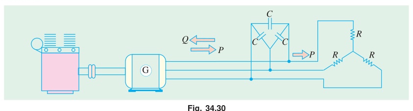
An induction generator still needs reactive (magnetizing) current to maintain its magnetic field. In grid-connected mode, the grid supplies reactive power. In islanded mode (no grid), capacitors must supply the reactive power.
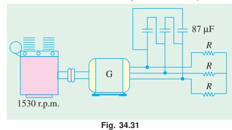
The capacitor bank must supply exactly the reactive power that the motor would have drawn at the same operating point.
Capacitance calculation:
At rated motor conditions: reactive power Q=3VLILsinϕ
For Δ-connected capacitors: each capacitor sees line voltage VL.
QC=3VL2/XC (per-phase capacitors in delta, QC total for 3-phase)
XC=3VL2/Q → C=1/(2πfXC)
Engine speed calculation
Full-load slip as motor: smotor=(Ns−NFL)/Ns. As generator, the rotor must run above Ns by the same magnitude of slip:
sgen=−smotor
Ngen=Ns(1−sgen)=Ns(1+smotor)
← T-20: Speed Control & Braking | 🏠 Index | T-22: 1-Phase IM Theory (DFRT) →