topicwise_answers_explanation/T-15_IM_Equivalent_Circuit.md
6.4 KB · commit d2f3b6e
← T-14: IM as Rotating Transformer | 🏠 Index | T-16: Torque Equations & Curves →
T-15: IM Equivalent Circuit
ECE 2207 — Explanation Answers (Sorted by Topic)
Topic Overview: This document compiles all semester final questions and explanation answers on IM Equivalent Circuit from 7 years of exams (2017–2024). Repeated questions appear once with all exam appearances noted.
T-15: Step-by-Step Derivation of the Induction Motor Equivalent Circuit
Appears in: 2017 Q3(a), 2020 Q5(c)
The physical challenge: different frequencies on stator and rotor
In a transformer, both primary and secondary windings operate at the identical electrical frequency f. In an induction motor, however, the stator operates at supply frequency f, but the rotor conductors rotate at mechanical speed N. The relative speed between the stator rotating magnetic field (Ns) and the rotor (N) is the slip speed sNs.
Consequently, the induced rotor EMF alternates at slip frequency: fr=sf
Because electrical circuits operating at different frequencies cannot be directly joined into a single equivalent mesh, we must convert the variable-frequency rotating rotor into a mathematically equivalent stationary circuit operating at the supply frequency f.
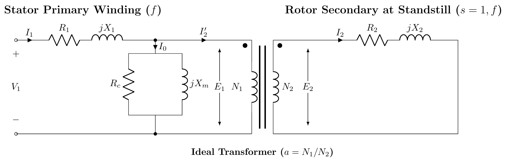
Step 1: Stator Model and Standstill Rotor (The Transformer Analogy at s=1)
At standstill (locked rotor, slip s=1), the rotor is stationary, and both stator and rotor operate at the supply frequency f.
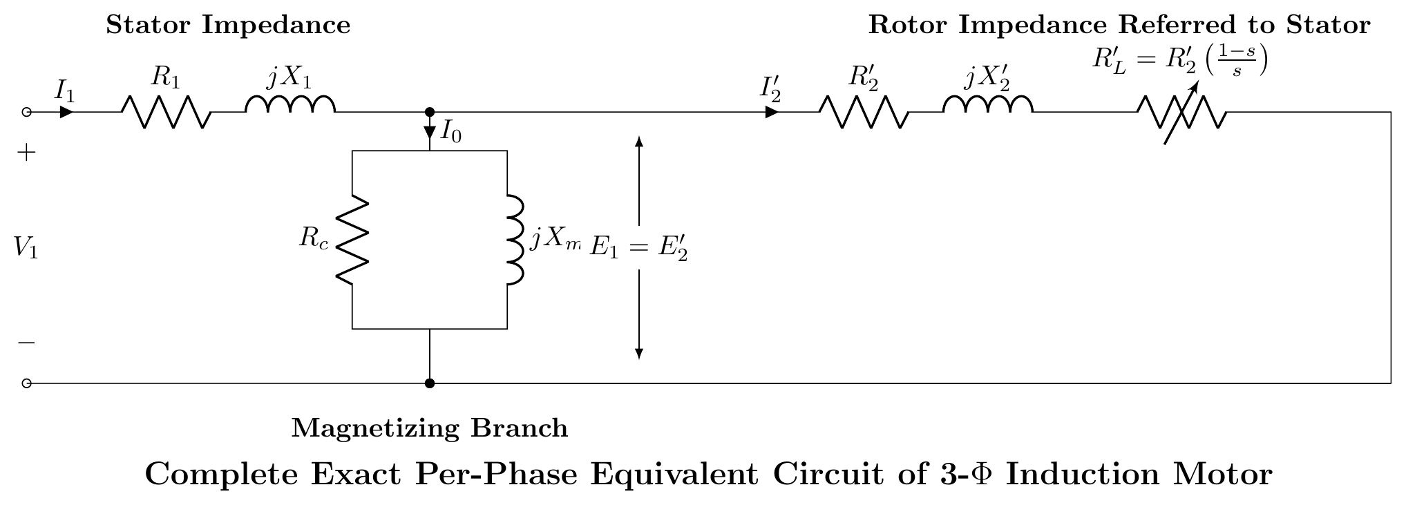
- The stator primary consists of winding resistance R1, leakage reactance jX1, and a parallel magnetizing branch (Rc∥jXm) carrying no-load excitation current I0 (Ic for core loss and Im for air-gap magnetization).
- The stator induced EMF E1 couples magnetically to the rotor standstill EMF E2 across the air gap via an ideal transformer of effective turns ratio a=N1/N2.
- The rotor winding has resistance R2 and standstill leakage reactance jX2, short-circuited on itself.
Step 2: Rotor Circuit at Any Running Slip s (Actual Rotor Frequency fr=sf)
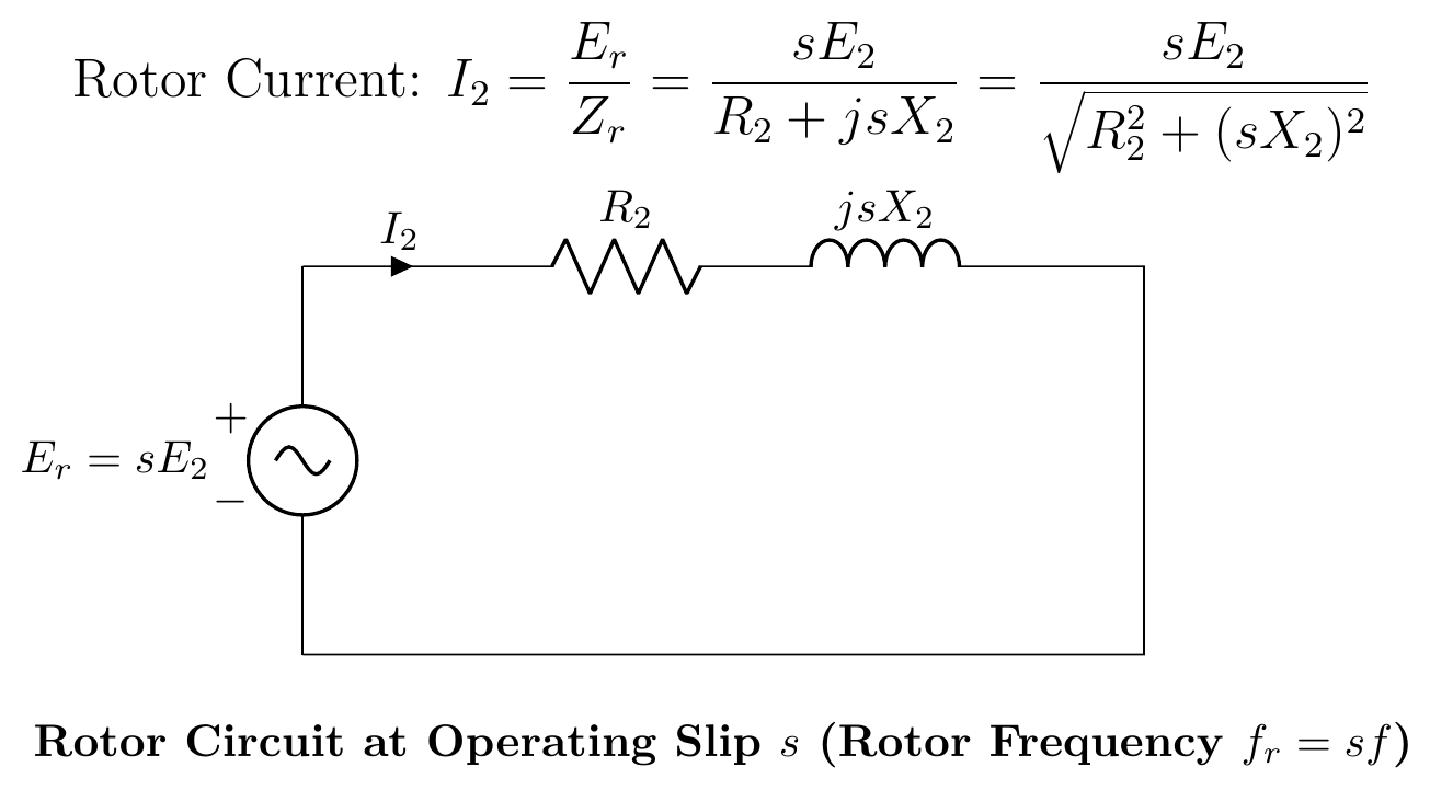
When the rotor rotates at mechanical speed N, the relative speed between the stator rotating magnetic field (Ns) and the rotor is (Ns−N)=sNs. Consequently:
- Rotor induced EMF: Er=sE2
- Rotor frequency: fr=sf
- Rotor leakage reactance: Xr=2πfrL2=2π(sf)L2=sX2
- Rotor resistance: R2 remains constant (independent of slip).
The rotor current per phase at running slip s is: I2=ZrEr=R22+(sX2)2sE2=R2+jsX2sE2
Step 3: Frequency Transformation to Stator Line Frequency f (Variable Resistance Model)
Because the stator operates at frequency f while the rotor operates at slip frequency sf, they cannot be coupled directly into a unified conductive circuit.
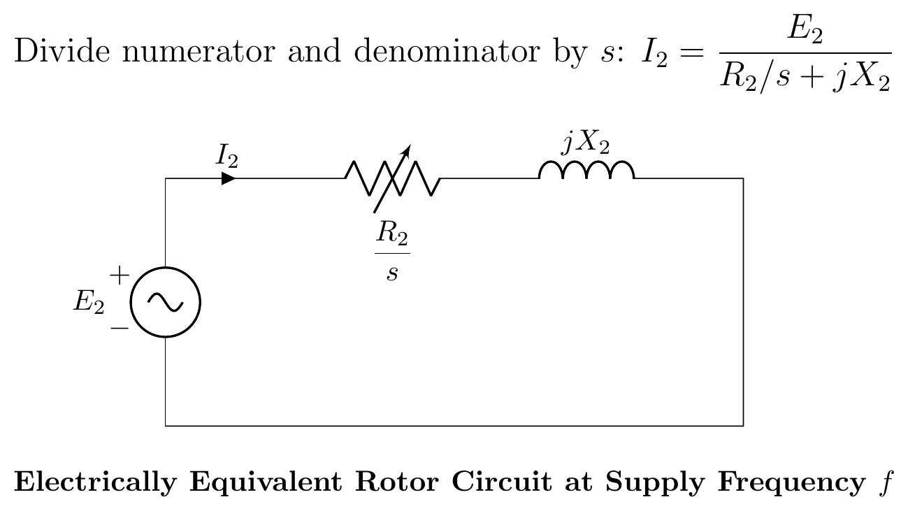
Dividing both the numerator and denominator of the rotor current expression by slip s: I2=sR2+jsX2ssE2=sR2+jX2E2
Physical Significance:
- The induced EMF is now fixed at E2 at constant line frequency f.
- The rotor leakage reactance is fixed at its standstill value jX2 at frequency f.
- The rotor resistance becomes a variable fictitious resistance sR2, which reflects the effect of mechanical rotation.
- Both stator and rotor models now operate at the same supply frequency f.
Step 4: Separation of Rotor Power (Copper Loss vs. Mechanical Power Output)
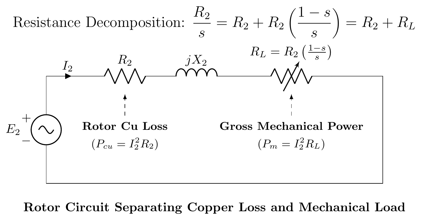
The total electrical power transferred across the air gap into the rotor per phase (Pg, air-gap power) is: Pg=I22(sR2)
We split the variable resistance sR2 into two components: sR2=R2+R2(s1−s)=R2+RL
- R2 (Constant): Actual rotor winding resistance, which accounts for the internal rotor copper loss: Pcu=I22R2
- RL=R2(s1−s) (Variable): Fictitious electrical load resistance representing the gross mechanical power developed by the rotor (Pm): Pm=I22RL=I22R2(s1−s)
Step 5: Referring Rotor to Stator (Complete Exact Per-Phase Equivalent Circuit)
By referring all rotor quantities across the ideal transformer to the stator side using the effective transformation ratio a=N1/N2 (where impedances scale by a2 and currents by 1/a):
- E2′=aE2=E1
- I2′=aI2
- R2′=a2R2
- X2′=a2X2
- RL′=a2RL=R2′(s1−s)
- Total rotor branch resistance: sR2′=R2′+RL′
The ideal transformer is eliminated, resulting in the Complete Exact Per-Phase Equivalent Circuit:
Step 6: Approximate Per-Phase Equivalent Circuit (Engineering Model)
Under normal load conditions, the stator impedance drop I1(R1+jX1) is negligible (≈2–5%). Shifting the shunt magnetizing branch (Rc∥jXm) directly across the stator supply terminals V1 simplifies calculation without substantial loss of accuracy:
- Total equivalent series resistance: R01=R1+R2′
- Total equivalent series leakage reactance: X01=X1+X2′
- Load resistance: RL′=R2′(s1−s)
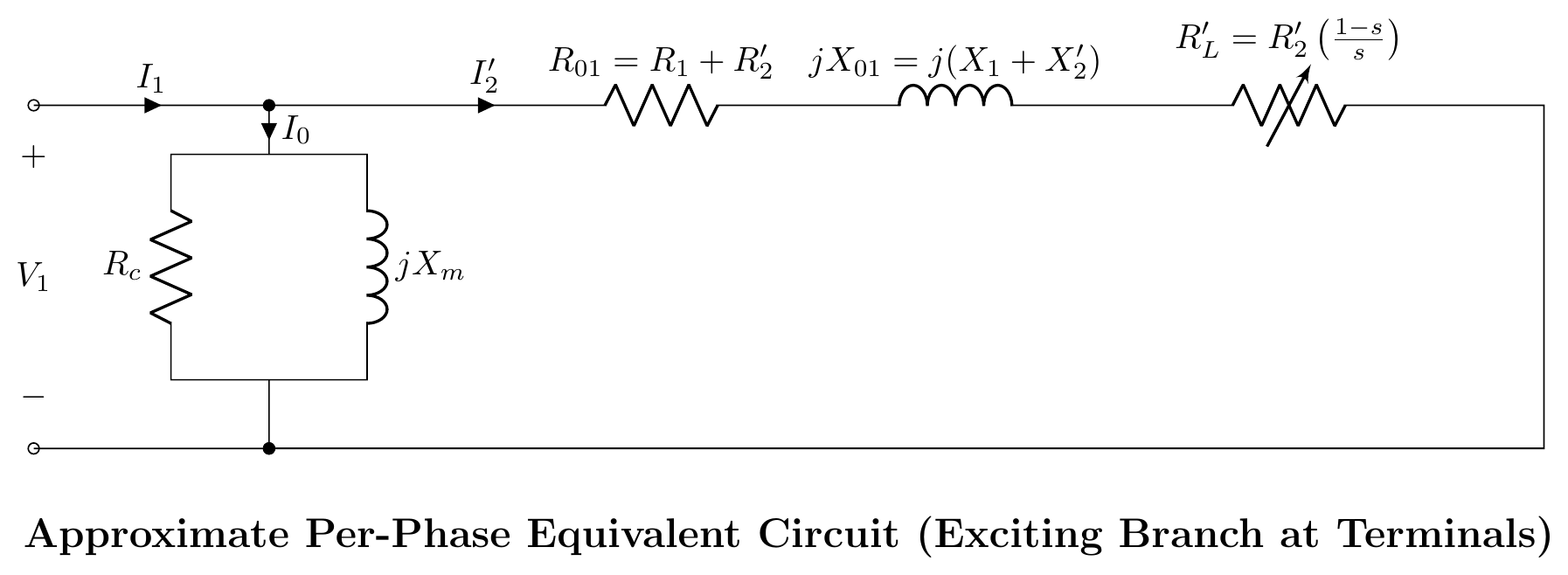
This complete per-phase model enables exact calculation of stator current, power factor, electromagnetic torque, developed power, and efficiency across the entire speed range.
← T-14: IM as Rotating Transformer | 🏠 Index | T-16: Torque Equations & Curves →