topicwise_answers_explanation/T-12_Rotating_Magnetic_Field.md
3.4 KB · commit d2f3b6e
← T-11: Misc Transformer Topics | 🏠 Index | T-13: Slip & Sync Speed →
T-12: Rotating Magnetic Field
ECE 2207 — Explanation Answers (Sorted by Topic)
Topic Overview: This document compiles all semester final questions and explanation answers on Rotating Magnetic Field from 7 years of exams (2017–2024). Repeated questions appear once with all exam appearances noted.
Q5(c): 2-phase supply produces RMF: proof and comparison with 3-phase
📋 Appeared in: 2021 Q5(c)
The proof
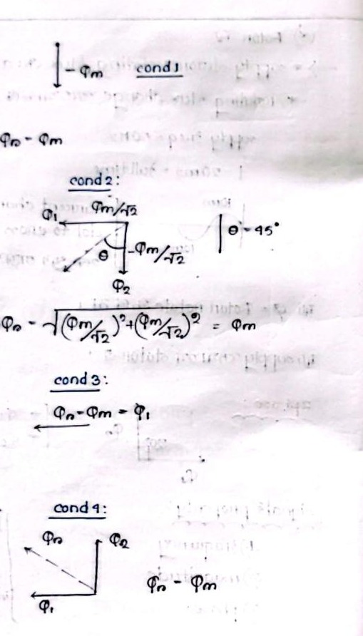
Two windings placed at 90° in space, fed by two-phase supply (90° apart in time):
Flux along X-axis: Φa=Φmsinωt Flux along Y-axis: Φb=Φmsin(ωt−90°)=−Φmcosωt
Resultant: Φr=Φa2+Φb2=Φm=constant
The field rotates at ω=2πf rad/s, giving Ns=120f/P rpm.
Comparison:
- 3-phase produces Φr=1.5Φm (50% larger than single-phase peak)
- 2-phase produces Φr=Φm (equal to single-phase peak)
- 3-phase is more efficient (higher flux per unit copper)
- 2-phase is only used in specialized applications (servo motors, certain instrumentation)
Q5(a): The RMF proof: 2024 version with emphasis on what each step means
📋 Appeared in: 2017 Q1(b), 2018 Q6(b), 2021 Q5(c), 2024 Q5(a)
The complete physical story
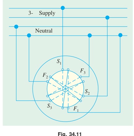
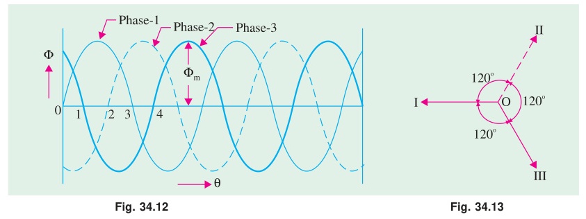
Three stator windings, physically separated by 120° in the stator bore, each carrying a current that is 120° displaced in time from the other two.
The key insight: each winding produces a field that pulsates along its own axis. It does not rotate. It alternates.
When you add three pulsating fields from three different fixed directions (120° apart), and each alternates at the same frequency but with a 120° time delay, a remarkable cancellation and reinforcement pattern emerges.
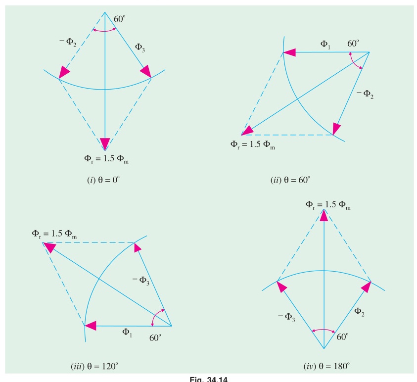
The mathematics showed: at every instant, the vector sum has constant magnitude 1.5Φm and rotates at angular frequency ω.
Why 1.5Φm and not 3Φm? Because all three phases never peak simultaneously. At any given moment, one phase might be at its peak while the other two are at intermediate values. The maximum achievable vector sum (given the 120° constraints) is 1.5Φm, not 3Φm.
Verify: At ωt=90°: ΦR=Φm, ΦY=−Φm/2, ΦB=−Φm/2. Vector sum: Φm+(−Φm/2)ej120°+(−Φm/2)e−j120°=Φm+(−Φm/2)(ej120°+e−j120°)=Φm−Φm×2×(−1/2)/2... simplifying: Φm−(−Φm/2)=1.5Φm (along the R-phase axis). ✓
← T-11: Misc Transformer Topics | 🏠 Index | T-13: Slip & Sync Speed →