topicwise_answers_explanation/T-10_Auto-Transformer.md
2.4 KB · commit d2f3b6e
← T-09: Vector Groups & Parallel | 🏠 Index | T-11: Misc Transformer Topics →
T-10: Auto-Transformer
ECE 2207 — Explanation Answers (Sorted by Topic)
Topic Overview: This document compiles all semester final questions and explanation answers on Auto-Transformer from 7 years of exams (2017–2024). Repeated questions appear once with all exam appearances noted.
Q3(b): Copper saving in auto-transformer: detailed analysis
📋 Appeared in: 2018 Q3, 2020 Q3(b)
Why some power doesn't need to be "transformed"
In a step-down auto-transformer (k=V2/V1<1):
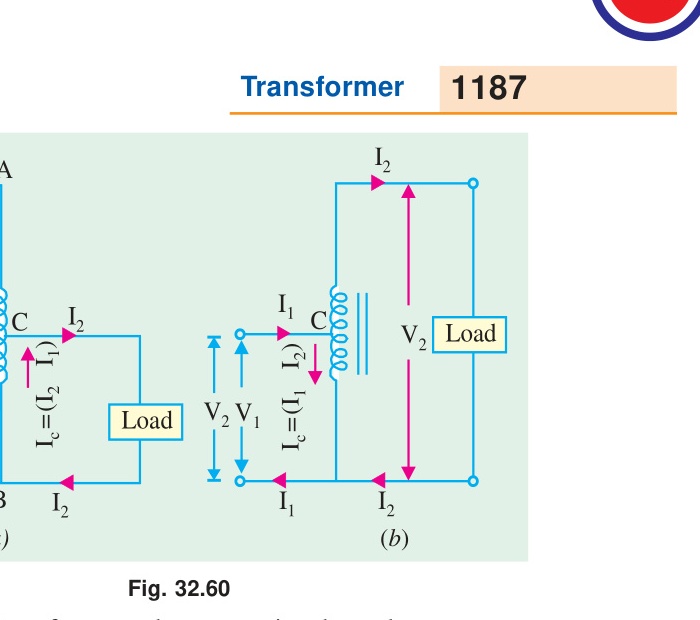
The output voltage V2 is present across the common winding (the lower section of the single winding). The series winding (top section) has voltage V1−V2 across it.
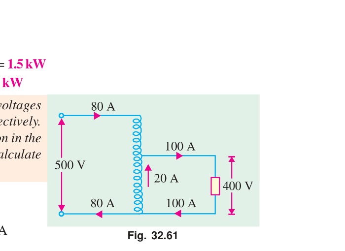
The output current I2 flows through the common winding. The series winding carries only I1 (the primary current).
Power through the series winding: Pseries=(V1−V2)×I1=(1−k)×V1I1=(1−k)S
This is the power that must be transformed magnetically. The rest, kS, is conducted directly.
The copper needed for the windings is proportional to the VA to be handled:
Series winding: Handles (1−k) fraction of full VA. Common winding: Current (I2−I1)=I2(1−k), voltage V2. VA =V2×I2(1−k)=kS×(1−k)/k=(1−k)S.
Total copper in auto-transformer ∝2(1−k)S. For ordinary transformer ∝2S.
WordinaryWauto=1−k,Copper saved=kS×(reference copper)
When is auto-transformer best used? When k is close to 1 (small voltage step). For k=0.9 (e.g., 415V/380V), copper saved is 90%. For k=0.5 (220V/110V), only 50% saved: still worthwhile. For k=0.1 (large ratio), only 10% saved: not economical.
Induction Motor Topics
← T-09: Vector Groups & Parallel | 🏠 Index | T-11: Misc Transformer Topics →