topicwise_answers_explanation/T-08_Scott_T-T_Connection.md
6.1 KB · commit d2f3b6e
← T-07: 3-Phase & Open-Delta | 🏠 Index | T-09: Vector Groups & Parallel →
T-08: Scott (T-T) Connection
ECE 2207 — Explanation Answers (Sorted by Topic)
Topic Overview: This document compiles all semester final questions and explanation answers on Scott (T-T) Connection from 7 years of exams (2017–2024). Repeated questions appear once with all exam appearances noted.
T-08: Scott (T-T) Connection: Conversion Between 3-Phase and 2-Phase
Appears in: 2018 Q4(a), 2018 Q4(b), 2019 Q4(b)
Why phase conversion is needed
Standard electrical power generation and transmission are universally 3-phase. However, certain heavy industrial loads: such as large electric arc furnaces, induction heating equipment, and two-phase AC servomotors: require balanced two-phase power (two equal voltages displaced by 90° in time).
Directly connecting a single-phase or two-phase load across a 3-phase line causes severe voltage unbalance, overheating nearby generators and motors. The Scott connection (invented by Charles F. Scott) provides a balanced conversion: it draws balanced 3-phase currents from the supply while delivering balanced 2-phase power to the load (or vice versa).
Construction and connection details
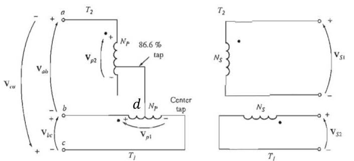
The scheme uses two single-phase transformers:
-
Main transformer (TM):
- The primary winding has N1 turns with a center tap D at exactly 50% turns (N1/2).
- Connected across two line terminals of the 3-phase supply: lines A and B.
- Primary voltage is the full line-to-line voltage VAB=VL.
-
Teaser transformer (TT):
- The primary winding has NT=23N1≈0.866N1 turns.
- Connected between the center tap D of the main transformer primary and the third line terminal C.
- Voltage across the teaser primary is the median of the equilateral voltage triangle: VDC=23VL≈0.866VL.
-
Secondaries:
- Both main and teaser secondaries have an equal number of turns N2.
- This ensures both output phase voltages have identical magnitude: V2M=V2T=V2.
Mathematical proof of 90° phase displacement
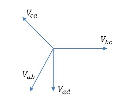
In a balanced 3-phase system, the line voltages form an equilateral triangle ABC with sides equal to VL:
- Let line voltage VAB=VL∠0° (horizontal reference).
- Center tap D divides AB into two equal halves: VAD=VDB=21VL∠0°.
- Vertex C is at distance VL from both A and B.
From equilateral triangle geometry, the altitude DC from the midpoint D to vertex C is perpendicular to base AB: VDC=VC−VD ∣VDC∣=VL2−(2VL)2=43VL2=23VL≈0.866VL
Because DC⊥AB, the phasor VDC is shifted by exactly 90° in time relative to VAB: VAB=VL∠0° VDC=23VL∠90°
Secondary induced EMFs
The secondary voltage of the main transformer is: V2M=VAB×N1N2=VLN1N2∠0°
The secondary voltage of the teaser transformer is: V2T=VDC×NTN2=(23VL∠90°)×23N1N2=VLN1N2∠90°
Notice how the factor 23 cancels out perfectly. The two output voltages have identical magnitudes and are in exact time quadrature (90° phase shift): ∣V2M∣=∣V2T∣andV2T leads V2M by 90°
This constitutes a true, balanced 2-phase electrical supply.
[2018 Q4(b)]: Worked Numerical Problem
📋 Appeared in: 2018 Q4(b)
Problem: Two T-connected transformers supply a 440V, 33 kVA balanced load from a 3300V balanced 3-phase supply. Find: (i) voltage and current rating of each coil, (ii) kVA rating of main and teaser.
Step-by-step physical solution
Given:
- 3-phase supply line voltage: VL=3300 V.
- 2-phase balanced load: Stotal=33 kVA, V2=440 V.
- Power per phase in 2-phase system: Sphase=33/2=16.5 kVA.
1. Secondary coil ratings (identical for both transformers):
- Secondary voltage: V2=440 V.
- Secondary current: I2=V2Sphase=440 V16500 VA=37.5 A
2. Main transformer primary coil ratings:
- Main primary is connected across lines A and B: V1,main=VL=3300 V
- Primary current: I1,main=V1,mainSphase=330016500=5.0 A
3. Teaser transformer primary coil ratings:
- Teaser primary has 0.866N1 turns and is connected from center-tap D to phase C: V1,teaser=23×3300=0.866×3300=2857.8 V≈2858 V
- Primary current (carries line current from phase C): I1,teaser=V1,teaserSphase=2857.816500=5.77 A
4. kVA rating of main and teaser transformers: kVAmain=V1,main×I1,main=3300 V×5.0 A=16.5 kVA kVAteaser=V1,teaser×I1,teaser=2857.8 V×5.77 A=16.5 kVA
Conclusion: Both transformers operate at identical apparent power ratings (16.5 kVA each), perfectly sharing the total 33 kVA load.
← T-07: 3-Phase & Open-Delta | 🏠 Index | T-09: Vector Groups & Parallel →