topicwise_answers_exam_style/T-04_Equivalent_Circuit.md
6.7 KB · commit d2f3b6e
← T-03: No-Load & Phasors | 🏠 Index | T-05: Voltage Regulation →
T-04: Equivalent Circuit
ECE 2207 — Exam-Style Answers (Sorted by Topic)
Topic Overview: This document compiles all semester final questions and exam-style answers on Equivalent Circuit from 7 years of exams (2017–2024). Repeated questions appear once with all exam appearances noted.
[2017 Q8(c)]
📋 Appeared in: 2017 Q8(c)
(c) 200/400V step-up transformer, parameters referred to LV side: Req=0.15Ω, Xeq=0.37Ω, Rc=600Ω, Xm=300Ω. Load: 10A at 0.8 pf lag (secondary). Find: (i) primary current, (ii) secondary terminal voltage. [05]
Given: Turns ratio a=N1/N2=200/400=0.5 (step-up), all parameters on LV (primary) side.
Load referred to primary side:
- Secondary current I2=10 A. Referred to primary: I2′=I2/a=10/0.5=20 A (but we need to be careful: referred secondary current to primary = I2×(N2/N1)=10×2=20 A).
Wait: parameters are referred to LV side. Secondary current (HV side) = 10 A. Referred to LV (primary): I2′=10×(N2/N1)=10×2=20 A at pf =0.8 lag.
Taking V2′ as reference on primary side:
Secondary terminal voltage referred to primary: V2′=200 V (at rated voltage the secondary is 400V, referred to primary = 400 × 0.5 = 200V).
Let V2′=200∠0° V, I2′=20∠−36.87° A
Approximate primary voltage (neglecting shunt branch for initial calc): V1=V2′+I2′(Req+jXeq) =200∠0°+20∠−36.87°×(0.15+j0.37)
I2′=20(0.8−j0.6)=16−j12
I2′(Req+jXeq)=(16−j12)(0.15+j0.37) =16(0.15)+16(j0.37)+(−j12)(0.15)+(−j12)(j0.37) =2.4+j5.92−j1.8+4.44 =6.84+j4.12
V1=(200+6.84)+j4.12=206.84+j4.12 ∣V1∣=206.842+4.122≈206.88 V
Primary current (including magnetizing branch):
Ic=RcV1=600206.88=0.345 A (in phase with V1) Im=XmV1=300206.88=0.690 A (lagging V1 by 90°)
No-load current: I0=Ic−jIm=0.345−j0.690
I1=I0+I2′=(0.345−j0.690)+(16−j12)=16.345−j12.69
∣I1∣=16.3452+12.692=267.2+161.1=428.3≈20.70 A
Secondary terminal voltage (actual): Referred back to secondary side: V2,actual=∣V2′∣×(N2/N1)=200×2=400 V
(In this simplified case, since we set V2′=200 V as reference, actual secondary =400 V with the given load conditions.)
[2020 Q1(b)]
📋 Appeared in: 2020 Q1(b)
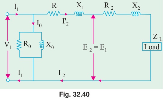
(b) Derive the equivalent circuit of a single-phase two-winding transformer. [04]
Step 1: Ideal transformer with no losses, no leakage: V2V1=N2N1=a,I1=aI2
Step 2: Add core loss and magnetizing current (shunt branch): Primary draws no-load current I0=Ic+jIm even at no load.
- Ic in phase with V1: represented by Rc=V1/Ic in shunt.
- Im lags V1 by 90°: represented by Xm=V1/Im in shunt.
Step 3: Add primary winding resistance and leakage reactance: Series elements R1 and jX1 on the primary side.
Step 4: Refer secondary to primary: Replace R2, jX2 with a2R2=R2′, ja2X2=jX2′ on the primary side.
Step 5: Final approximate equivalent circuit (shunt branch at input):
V1→[R1+jX1+R2′+jX2′]→E1
Shunt branch (Rc∥jXm) connected across V1.
For simplicity, combine series elements: R01=R1+R2′,X01=X1+X2′
[2020 Q3(c)]
📋 Appeared in: 2020 Q3(c)
(c) Step-by-step equivalent circuit of a transformer referred to primary side. [05]
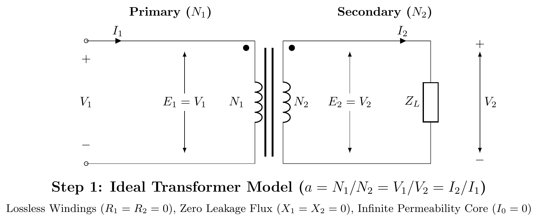
1. Ideal Transformer Core Model:
Start with an ideal core (zero winding resistance, zero leakage flux, infinite permeability, zero core loss).
E1=aE2,I1=I2/awhere a=N1/N2
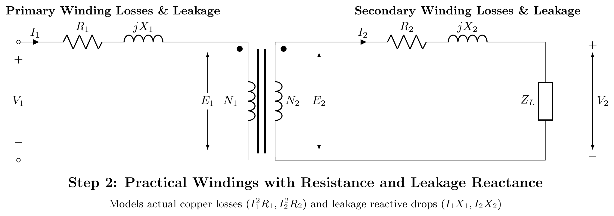
2. Winding Resistances and Leakage Reactances:
Add practical winding series resistance (R1,R2) and leakage reactance (X1,X2) on both sides.
V1=E1+I1(R1+jX1),E2=V2+I2(R2+jX2)
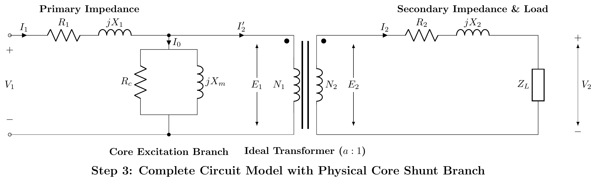
3. Core Excitation Shunt Branch:
Add a parallel branch across E1 to model core iron loss (Rc) and magnetizing reactance (Xm). The total no-load current is I0=Ic+Im.
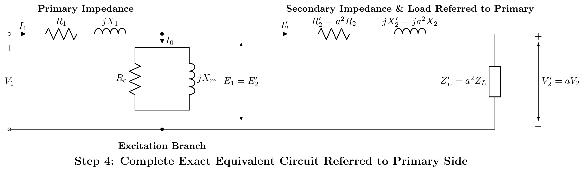
4. Transferring Secondary to Primary (Exact Equivalent Circuit):
To eliminate the ideal transformer, transfer secondary parameters to the primary using a2:
R2′=a2R2,X2′=a2X2,V2′=aV2,I2′=I2/a
5. Approximate Equivalent Circuit:
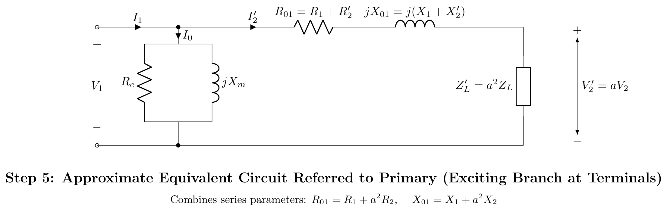
Since I0 is small and the primary voltage drop I0(R1+jX1) is negligible, move the shunt branch to the primary terminals. The series impedances combine to R01=R1+R2′ and X01=X1+X2′.
[2024 Q4(c)]
📋 Appeared in: 2024 Q4(c)
(c) Obtain the equivalent circuit of a transformer referred to the primary side. [03, CO1]
Referring secondary to primary:
Replace all secondary quantities with primary-referred (primed) values: R2′=a2R2,X2′=a2X2,E2′=aE2=E1,ZL′=a2ZL
Final equivalent circuit referred to primary:
Series branch: R01=R1+R2′, X01=X1+X2′ (total series impedance).
Shunt branch: Rc∥jXm (at primary terminals: approximate circuit).
In the approximate equivalent circuit, the shunt branch is moved to the primary input terminals (before R1, X1). This simplifies calculation without significant error for most power transformers.
← T-03: No-Load & Phasors | 🏠 Index | T-05: Voltage Regulation →