boss_notes/T-23_1Phase_Starting_Methods.md
10.4 KB · commit d2f3b6e
← T-22: DFRT & 1-Phase IM | 🏠 Index | T-24: Miscellaneous IM Topics →
T-23: Single-Phase IM Starting Methods
Section: B | Priority: 🔴 MUST | Exam Frequency: 6/7 years Sources: VK Mehta Ch-9 (Art. 9.5-9.14), Theraja Ch-35, Slides L-08, L-09
Why This Topic Matters
1-phase IM starting methods appeared in 6 out of 7 papers. Types include: capacitor-start (2017, 2020, 2023, 2024), capacitor-start-capacitor-run (2021, 2024), shaded pole (2023, 2024), split-phase (2017, 2018), and capacitor calculation numericals (2018, 2019, 2021). These questions range from 3-6 marks. This is the second most guaranteed topic after DFRT.
📝 Key Definitions
Capacitor-Start Motor: "An auxiliary winding with a capacitor in series is placed 90° apart from the main winding. The capacitor advances the phase of auxiliary current. With proper capacitor value, the phase difference between main and auxiliary current approaches 90°, creating a rotating field for starting." — VK Mehta, Art. 9.8
Shaded-Pole Motor: "A short-circuited copper band (shading band) is placed around a portion of each stator pole face. The flux in the shaded portion lags behind the flux in the unshaded portion, creating a sweeping effect from unshaded to shaded side." — VK Mehta, Art. 9.12
Classification of 1-Phase IM Starting Methods
| Motor Type | Principle | Starting Torque | Running pf | Applications |
|---|---|---|---|---|
| Split-Phase | High-Ra auxiliary winding | 150-200% FL | Moderate | Fans, pumps, small tools |
| Capacitor-Start | Capacitor in series with auxiliary | 200-400% FL | Moderate | Compressors, conveyors |
| Permanent-Split Cap | Capacitor always in circuit | 50-100% FL | Good | Fans, blowers (quiet) |
| Cap-Start, Cap-Run | Cst (start) + Crun (run) | 200-350% FL | Good | Compressors, pumps |
| Shaded-Pole | Copper band on pole face | 40-60% FL | Poor | Small fans, timers |
Capacitor-Start Motor
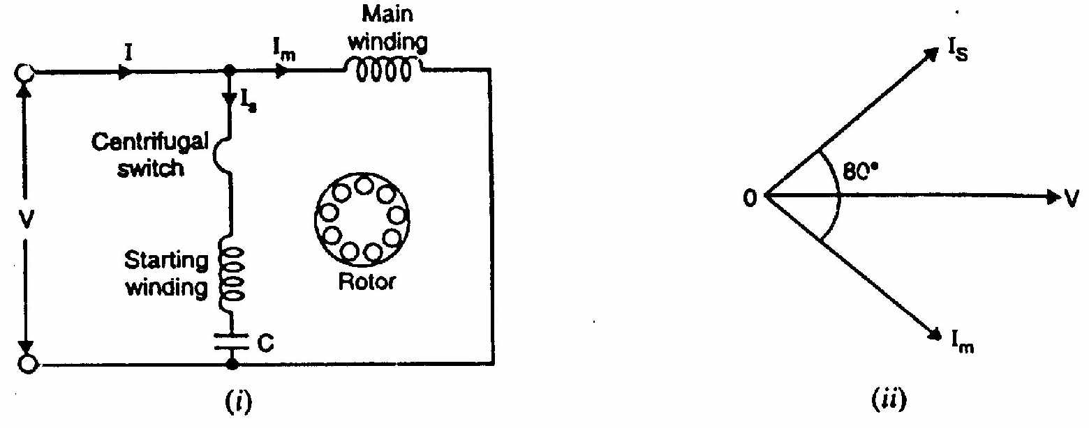
Construction:
- Main winding (M) and auxiliary winding (A) placed 90° apart in space
- Capacitor in series with auxiliary winding
- Centrifugal switch disconnects auxiliary winding at ~75% of Ns
Operation:
- The capacitor makes the auxiliary current Ia LEAD the voltage
- The main current Im LAGS the voltage
- Total phase difference between Ia and Im approaches 90°
- 90° time displacement + 90° space displacement = rotating field
- Starting torque is high (200-400% FL)
- At ~75% speed, switch opens. Motor runs on main winding only.
Capacitor-Start, Capacitor-Run Motor
Two capacitors:
- Cst (large, starting): in circuit only during starting. Switched out by centrifugal switch.
- Crun (small, running): permanently in circuit.
Starting: Cst∥Crun gives large capacitance. Nearly 90° phase split. High starting torque.
Running: Only Crun in circuit. Optimized for running efficiency and power factor. Smoother, quieter than capacitor-start-only motor.
Shaded-Pole Motor
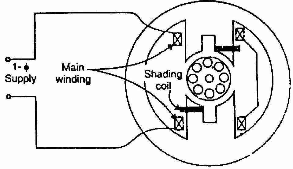
Construction: Salient stator poles. Short-circuited copper band (shading ring) around part of each pole.
Operation:
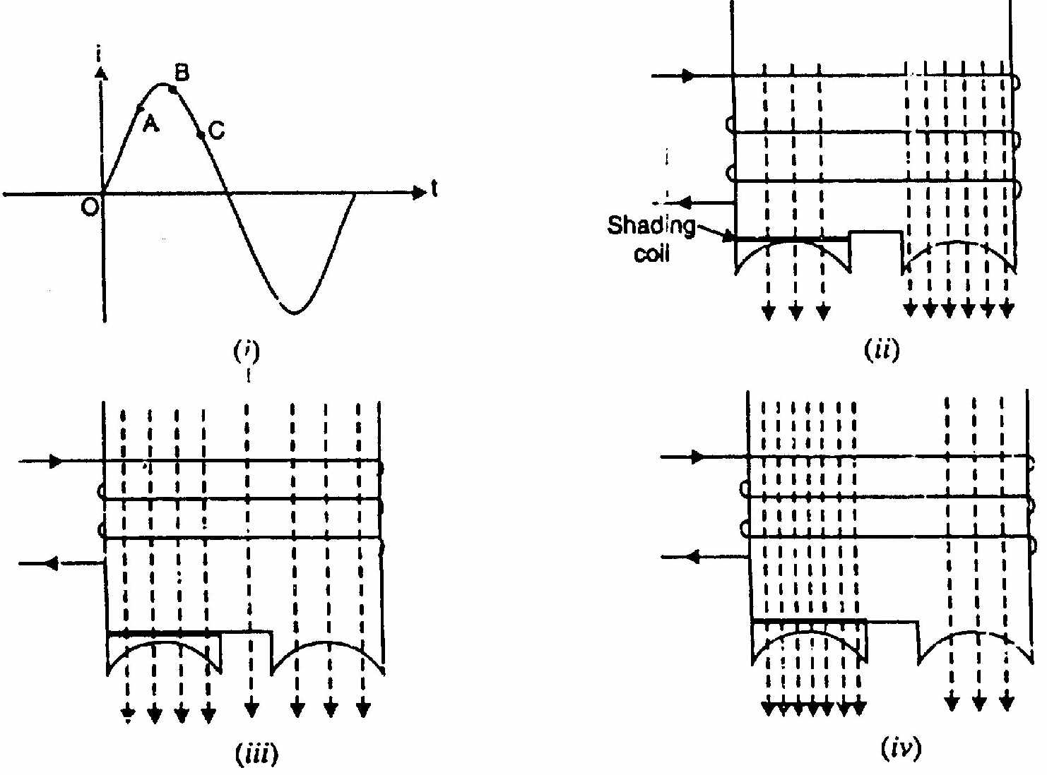
- Alternating flux through the pole induces current in the shading ring (Lenz's law)
- Ring current opposes flux change in shaded portion
- Flux in shaded portion LAGS behind flux in unshaded portion
- This time lag creates a sweeping effect: unshaded → shaded
- Small starting torque in one direction
Characteristics: Very simple, no switches, no capacitors. Low starting torque (40-60% FL). Low efficiency. Fixed direction. Small sizes only (fans, display motors, hair dryers).
Split-Phase (Resistance) Motor
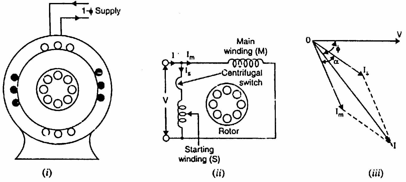
Construction: Auxiliary winding has higher resistance and lower reactance than main winding. Placed 90° apart in space.
Operation: Higher Ra/Xa ratio makes Ia lag less than Im. Phase difference = 30°-40° (not 90°). Moderate starting torque.
Capacitor Calculation for Maximum Starting Torque
For maximum starting torque, Im and Ia must be 90° apart in time.
Method:
- Find main winding angle: ϕm=tan−1(Xm/Rm)
- For 90° total: Ia must lead V by (90°−ϕm)
- Auxiliary circuit must be capacitive: net angle = −(90°−ϕm) leading
- XC=Xa+Ratan(90°−ϕm)
- C=1/(2πfXC)
🏆 Golden Questions (Past Exam Archive)
🎯 Q1: Describe any two methods of making a 1-phase IM self-starting.
Appeared: 2023 Q8(b), 2024 Q8(b) — (6 marks)
Full Answer:
Method 1: Capacitor-Start Motor
Auxiliary winding placed 90° from main winding. Capacitor in series with auxiliary. Capacitor makes Ia lead V. Phase difference between Ia and Im approaches 90°. 90° time split + 90° space split = RMF. Starting torque = 200-400% of FL. Centrifugal switch disconnects auxiliary at ~75% speed.
Method 2: Shaded-Pole Motor
Short-circuited copper band on part of each pole face. Alternating flux induces current in shading ring (Lenz's law). Flux in shaded portion lags behind unshaded. Creates sweeping effect from unshaded to shaded side. Small starting torque. Very simple, no switches. Low efficiency. For small motors only.
🎯 Q2: 230V, 50 Hz capacitor-start motor. Main: 100V, 2A, 40W. Auxiliary: 80V, 1A, 50W. Find capacitance for max starting torque.
Appeared: 2018 Q8(c) — (4 marks)
Full Answer:
Main winding: Zm=100/2=50Ω, Rm=40/4=10Ω, Xm=502−102=49Ω
ϕm=cos−1(10/50)=78.46° lagging
Auxiliary winding: Za=80/1=80Ω, Ra=50/1=50Ω, Xa=802−502=62.45Ω
For Ia to lead V by (90°−78.46°)=11.54°:
tan(11.54°)=(XC−Xa)/Ra
XC=Xa+Ratan(11.54°)=62.45+50×0.204=72.65Ω
C=2π×50×72.651=43.8μF
🎯 Q3: 250W, 230V, 50 Hz motor. Zm=(4.5+j3.7)Ω, Za=(9.5+j3.5)Ω. Find starting capacitor for quadrature currents.
Appeared: 2021 Q7(c) — (4 marks)
Full Answer:
ϕm=tan−1(3.7/4.5)=39.43° lagging
For Ia 90° ahead of Im: Ia must lead V by (90°−39.43°)=50.57°
tan(50.57°)=(XC−Xa)/Ra=(XC−3.5)/9.5
XC−3.5=9.5×1.213=11.52
XC=15.02Ω
C=2π×50×15.021=211.8μF
🎯 Q4: How does a capacitor-start-and-run motor operate?
Appeared: 2021 Q7(b) — (4 marks)
Full Answer:
Two capacitors: Cst (large) for starting, Crun (small) for running.
Starting: Cst and Crun in parallel. Large capacitance gives nearly 90° phase split. High starting torque (200-350% FL).
Running: Centrifugal switch disconnects Cst at ~75% speed. Motor runs with Crun only. Optimized for efficiency, power factor, and quiet operation. Better than capacitor-start (auxiliary stays on) or permanent-split (higher starting torque).
🎯 Q5: Why does a permanent-split capacitor motor run more quietly than a capacitor-start motor?
Appeared: 2017 Q4(b) — (4 marks)
Full Answer:
In a capacitor-start motor, the auxiliary winding is disconnected by a centrifugal switch at ~75% speed. After disconnection, the motor runs on the main winding only. This produces a pulsating field (not rotating). Pulsating torque causes vibration and noise. The switch click itself adds noise.
In a permanent-split capacitor motor, the auxiliary winding and capacitor remain connected at all times. The motor operates as a two-phase machine (approximate 90° phase shift) during both starting and running. The field is more nearly rotating at all speeds. No switch click. No current surge. Smoother, quieter operation.
🎯 Q6: Prove Xc=Xa+rarm/(Zm+Xm) for max starting torque of capacitor split-phase motor.
Appeared: 2019 Q6(b) — (4 marks)
Full Answer:
For maximum starting torque, Im and Ia must be 90° apart.
Main winding: Zm=rm+jXm. Main current Im lags V by ϕm.
For 90° between Im and Ia, the auxiliary impedance angle must satisfy:
From phasor geometry and the condition that real and imaginary parts of Im⋅Ia∗ give zero real product:
Xc=Xa+Xm+Zmrarm
This ensures the auxiliary current leads the main current by exactly 90°, producing maximum starting torque.
Exam Variants
| Year | Question | Marks | Type |
|---|---|---|---|
| 2017 Q4(b) | Permanent-split vs cap-start noise | 4 | Conceptual |
| 2017 Q4(c) | How auxiliary winding gives starting torque | 4 | Theory |
| 2018 Q8(b) | Split-phase phasor diagram | 4 | Theory |
| 2018 Q8(c) | Capacitor calculation numerical | 4 | Numerical |
| 2019 Q6(b) | Prove Xc formula | 4 | Derivation |
| 2020 Q7(a) | Describe one starting method | 3 | Theory |
| 2021 Q7(b) | Cap-start cap-run operation | 4 | Theory |
| 2021 Q7(c) | Capacitor calculation | 4 | Numerical |
| 2023 Q8(b) | Two starting methods | 6 | Theory |
| 2024 Q8(b) | Two types of 1-phase IM | 6 | Theory |
⚡ Exam Tips & Common Mistakes
- Capacitor-start is the most commonly tested. Know the circuit, phasor diagram, and principle.
- For capacitor numericals: The key equation is tan(90°−ϕm)=(XC−Xa)/Ra.
- Don't confuse the three capacitor motor types. Start-only, run-only (permanent-split), and start+run (two-value).
- Shaded-pole direction is fixed: unshaded to shaded. Cannot be reversed without physical modification.
- The centrifugal switch operates at ~75% of Ns. Not at full speed.
🔗 Related Topics
- T-22: DFRT & 1-Phase IM — Why starting methods are needed
- T-24: Miscellaneous IM Topics — Single phasing, AC motor classification
← T-22: DFRT & 1-Phase IM | 🏠 Index | T-24: Miscellaneous IM Topics →