boss_notes/T-12_Rotating_Magnetic_Field.md
9.7 KB · commit d2f3b6e
← T-11: Miscellaneous Transformer Topics | 🏠 Index | T-13: Slip & Basics →
T-12: Rotating Magnetic Field (RMF)
Section: B | Priority: 🔴 MUST | Exam Frequency: 5/7 years Sources: Theraja Ch-34 (Art. 34.6-34.8), VK Mehta Ch-8 (Art. 8.3-8.4), Slides L-01, L-02
Why This Topic Matters
The 3-phase RMF proof appeared in 5 out of 7 papers (2017, 2018, 2020, 2021, 2024). It is the foundation of every induction motor. Without a rotating field, there is no torque. This proof carries 5-8 marks and is one of the highest-scoring derivations in Section B. The 2-phase RMF proof appeared in 2021.
📝 Key Definitions
Induction Motor: "In a.c. motors, the rotor does not receive electric power by conduction but by induction in exactly the same way as the secondary of a 2-winding transformer receives its power from the primary. That is why such motors are known as induction motors. In fact, an induction motor can be treated as a rotating transformer i.e. one in which primary winding is stationary but the secondary is free to rotate." — Theraja, Art. 34.2
Rotating Magnetic Field: "When stationary coils, wound for two or three phases, are supplied by two or three-phase supply respectively, a uniformly-rotating (or revolving) magnetic flux of constant value is produced." — Theraja, Art. 34.6
Synchronous Speed: "The speed at which the rotating magnetic field revolves is called the synchronous speed (Ns). For a machine with P poles: Ns=120f/P r.p.m." — VK Mehta, Art. 8.3
How a 3-Phase Supply Creates a Rotating Field
Three stator windings are placed 120° apart in space. Each carries current that is 120° apart in time. Each winding creates a pulsating flux along its own axis. The vector sum of these three pulsating fluxes is a rotating flux of constant magnitude.
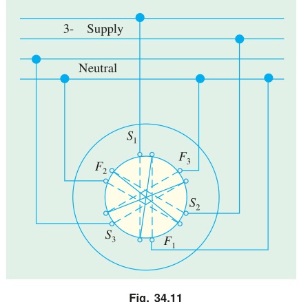
The key insight: no individual flux rotates. Each flux pulsates along a fixed axis. But the vector sum sweeps around the stator at synchronous speed.
3-Phase RMF: Mathematical Proof
This is the most important proof in Section B. Know every step.
Setup: Three windings 120° apart in space. Balanced 3-phase supply:
ΦR=Φmsinωt
ΦY=Φmsin(ωt−120°)
ΦB=Φmsin(ωt+120°)
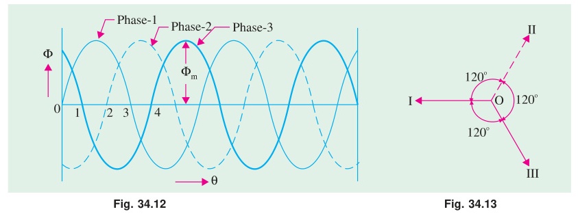
Step 1: Resolve into X and Y components.
Take R-phase axis as the +X reference. Y-phase axis is at 120° from X. B-phase axis is at 240° from X.
X-component:
Φx=ΦRcos0°+ΦYcos120°+ΦBcos240°
=Φmsinωt+Φmsin(ωt−120°)(−21)+Φmsin(ωt+120°)(−21)
Step 2: Simplify using trig identity sin(A−B)+sin(A+B)=2sinAcosB:
Φx=Φmsinωt−21Φm⋅2sinωtcos120°
=Φmsinωt−21Φm⋅2sinωt⋅(−21)
=Φmsinωt+21Φmsinωt=23Φmsinωt
Y-component:
Φy=ΦYsin120°+ΦBsin240°
=Φmsin(ωt−120°)⋅23+Φmsin(ωt+120°)⋅(−23)
Using sin(A−B)−sin(A+B)=−2cosAsinB:
=23Φm⋅(−2cosωtsin120°)=23Φm⋅(−2cosωt)⋅23
=−23Φmcosωt
Step 3: Find magnitude.
Φr=Φx2+Φy2=(23Φm)2(sin2ωt+cos2ωt)
Φr=23Φm=1.5Φm=constant
Step 4: Find rotation speed.
θ=tan−1(ΦxΦy)=tan−1(sinωt−cosωt)=ωt−90°
dtdθ=ω=2πf⟹Ns=P120f rpm
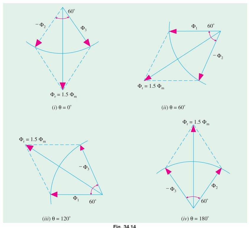
Conclusion: The 3-phase supply produces a rotating magnetic field of constant magnitude 1.5Φm, rotating at synchronous speed Ns=120f/P rpm. (Proved)
2-Phase RMF: Mathematical Proof
Setup: Two windings placed 90° apart in space. Balanced 2-phase supply:
Φa=Φmsinωt(along X-axis)
Φb=Φmsin(ωt−90°)=−Φmcosωt(along Y-axis)
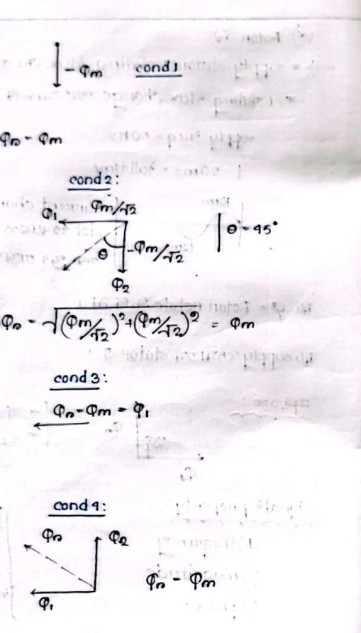
Magnitude:
Φr=Φa2+Φb2=Φm2sin2ωt+Φm2cos2ωt=Φm=constant
Space angle:
θ=tan−1(sinωt−cosωt)=ωt−90°
dtdθ=ω⟹Ns=P120f rpm
Result: 2-phase produces RMF of magnitude Φm at synchronous speed. Compare: 3-phase produces 1.5Φm (50% stronger).
Reversing Direction of Rotation
To reverse the direction of rotation of a 3-phase IM, interchange any two of the three supply lines. This changes the phase sequence from R-Y-B to R-B-Y. The rotating field now rotates in the opposite direction.
🏆 Golden Questions (Past Exam Archive)
🎯 Q1: Prove that a 3-phase supply produces a rotating magnetic field of constant magnitude 1.5Φm at synchronous speed.
Appeared: 2017 Q1(b), 2018 Q6(b), 2024 Q5(a) — (5-8 marks)
Full Answer:
See 3-Phase RMF: Mathematical Proof above for the complete derivation. The proof shows:
- Three windings 120° apart in space carry currents 120° apart in time
- Resolve all three pulsating fluxes into X and Y components
- X-component = 23Φmsinωt
- Y-component = −23Φmcosωt
- Magnitude = (23Φm)2(sin2ωt+cos2ωt)=1.5Φm (constant)
- Space angle θ=ωt−90°, so field rotates at ω=2πf, giving Ns=120f/P rpm
🎯 Q2: Show that a 2-phase supply produces a rotating magnetic field at synchronous speed.
Appeared: 2021 Q5(c) — (5 marks)
Full Answer:
Two windings placed 90° apart in space. Balanced 2-phase supply creates fluxes:
Φa=Φmsinωt(X-axis),Φb=−Φmcosωt(Y-axis)
Magnitude: Φr=Φm2sin2ωt+Φm2cos2ωt=Φm (constant)
Space angle: θ=tan−1(−cosωt/sinωt)=ωt−90°
Speed: dθ/dt=ω=2πf⟹Ns=120f/P rpm
The 2-phase supply produces a rotating field of constant magnitude Φm (not 1.5Φm as in 3-phase) at synchronous speed. (Proved)
🎯 Q3: What is an electrical machine? Describe the principle of operation of a 3-phase induction motor.
Appeared: 2019 Q5(a) — (4 marks)
Full Answer:
Electrical machine: A device that converts electrical energy to mechanical energy (motor) or mechanical energy to electrical energy (generator) using electromagnetic induction.
3-phase IM operating principle:
- Three-phase balanced AC supply to the stator creates a rotating magnetic field of magnitude 1.5Φm at synchronous speed Ns=120f/P rpm.
- The RMF sweeps across the stationary rotor conductors. The relative motion induces EMF in the rotor bars (Faraday's law).
- The induced EMF drives current through the short-circuited rotor bars (squirrel cage) or through external resistance (slip-ring motor).
- Current-carrying rotor conductors in the stator magnetic field experience a force (Lorentz force). This force produces torque.
- The rotor spins in the direction of the RMF (Lenz's law: rotor tries to reduce relative motion).
- The motor always runs at N<Ns (slip s>0). If N=Ns, relative motion is zero, EMF is zero, current is zero, torque is zero. So the motor can never reach synchronous speed.
Exam Variants
| Year | Question | Key Points |
|---|---|---|
| 2017 Q1(b) | Prove 3-phase RMF | Φr=1.5Φm, rotates at Ns |
| 2018 Q6(b) | Prove 3-phase RMF | Same proof |
| 2019 Q5(a) | IM operating principle | RMF + Faraday + Lenz |
| 2021 Q5(c) | Prove 2-phase RMF | Φr=Φm, rotates at Ns |
| 2024 Q5(a) | Prove 3-phase RMF (8 marks) | Full vector proof |
⚡ Exam Tips & Common Mistakes
- State assumptions at the start. Write "three identical windings, 120° apart in space, carrying balanced 3-phase currents 120° apart in time." This earns setup marks.
- Don't confuse 1.5Φm with 3Φm. All three phases never peak at the same time. The maximum vector sum is 1.5Φm.
- Show the trig identity you use. The examiner wants to see sin(A−B)+sin(A+B)=2sinAcosB. Don't skip this step.
- 2-phase produces Φm, not 1.5Φm. If asked to compare, state this clearly.
- Know how to reverse rotation. Swap any two supply lines. One sentence, but it carries 1-2 marks.
🔗 Related Topics
- T-13: Slip & Basics — What happens once the RMF starts spinning
- T-22: DFRT & 1-Phase IM — What happens with only one phase (no RMF, just pulsating field)
- T-15c: Torque-Speed Curves — How torque depends on slip
← T-11: Miscellaneous Transformer Topics | 🏠 Index | T-13: Slip & Basics →