boss_notes/T-08_Scott_Connection.md
6.1 KB · commit d2f3b6e
← T-07b: Open Delta | 🏠 Index | T-09: Vector Groups →
T-08: Scott (T-T) Connection
Section: A | Priority: 🟡 MEDIUM | Exam Frequency: 3/7 years Sources: Theraja Ch-33 (Art. 33.10), VK Mehta Ch-7 (Art. 7.37), Slides L-11 S20–S24
Why This Topic Matters
The Scott connection appeared in 3/7 papers (2018, 2019, 2024). When asked, it carries 4-6 marks. The question is always: "Explain the Scott connection with a diagram" and sometimes includes a numerical.
📝 Key Definitions
Scott (T-T) connection: "The Scott connection is a means of converting a 3-phase supply to a 2-phase supply, or vice versa, using two single-phase transformers. One transformer is called the 'main' (or 'T') transformer and the other is called the 'teaser' transformer. The teaser primary has 3/2 (= 86.6%) of the main transformer primary turns." — VK Mehta, Art. 7.37
How the Scott Connection Works
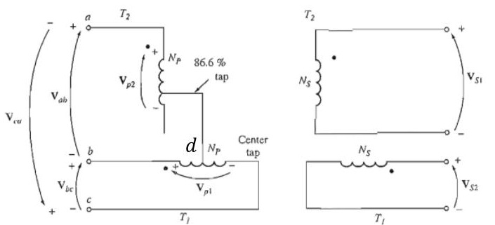
Main transformer: Primary connected between phases A and B (full line voltage VAB). Secondary provides one phase of the 2-phase output.
Teaser transformer: Primary connected from the midpoint (M) of the main transformer primary to phase C. The voltage from M to C:
VMC=23×VL
This is the height of the equilateral voltage triangle. The teaser primary needs 23=86.6% of the main transformer turns.
Why the outputs are 90° apart:
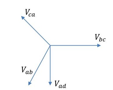
VAB is a line voltage. VMC is perpendicular to VAB in the phasor diagram (midpoint M bisects AB, so MC is the perpendicular bisector). The two secondary voltages inherit this 90° separation. Result: balanced 2-phase output.
🏆 Golden Questions (Past Exam Archive)
🎯 Q1: Explain the Scott connection with necessary diagrams.
Appeared: 2018 Q4(a), 2024 Q4(d) — 4 marks
Full Answer:
The Scott (T-T) connection converts 3-phase power to 2-phase power using two single-phase transformers.
Two transformers required:
(1) Main transformer: Standard transformer. Primary connected between two phases (e.g., A and B). Full line voltage VAB appears across its primary.
(2) Teaser transformer: Primary connected from the midpoint (M) of the main transformer primary to the third phase (C). Its primary has 3/2=86.6% of the main transformer's turns, because the voltage from midpoint M to C is VMC=(3/2)VL (the height of the equilateral voltage triangle).
Why 90° separation: In a balanced 3-phase system, the voltage from the midpoint of one line voltage to the third phase is always perpendicular to that line voltage. VAB is horizontal in the phasor diagram, VMC is vertical. The two secondaries inherit this 90° separation, producing a balanced 2-phase output.
Applications: Electric arc furnace power supplies, powering 2-phase induction motors, converting 2-phase to 3-phase (reverse operation is possible because transformers are reciprocal devices).
🎯 Q2: Can you convert 3-phase to 2-phase or vice versa? If yes, explain.
Appeared: 2019 Q4(b) — 4 marks
Full Answer:
Yes. This is done using the Scott (T-T) connection.
Two single-phase transformers are needed:
(1) Main transformer: Primary connected between two phases of the 3-phase supply (e.g., lines A and B). Secondary provides one phase of the 2-phase output.
(2) Teaser transformer: Primary connected from the mid-point of the main transformer primary to the third line (C). The teaser primary has 3/2 (86.6%) of the main transformer's turns. Secondary provides the second phase of the 2-phase output, exactly 90° displaced from the first.
Why it works: The two primary voltages are 90° apart geometrically in the phasor diagram. The line-to-midpoint voltage (VMC) is perpendicular to the line-to-line voltage (VAB) in a balanced 3-phase system. This 90° separation transfers to the two secondary voltages, giving a balanced 2-phase output.
Reverse (2-phase to 3-phase): Connect the two-phase supply to the secondaries. The 3-phase supply comes from the primaries. The same transformation works in reverse because transformers are reciprocal devices.
🎯 Q3: Two T-connected transformers supply 440V, 33 kVA balanced load from 3300V 3-phase. Find ratings.
Appeared: 2018 Q4(b) — 4 marks
Full Answer:
Given: Supply VL=3300 V (3-phase). Load: 440V, 33 kVA (2-phase).
Secondary voltages (2-phase, equal): V2=440 V per phase.
Secondary current per phase: I2=(S/2)/V2=(33000/2)/440=37.5 A
Main transformer primary: Connected across A-B: V1,main=VL=3300 V
I1,main=V1,mainS/2=330016500=5.0 A
Teaser transformer primary: Connected from midpoint of AB to C:
V1,teaser=23×VL=0.866×3300=2858 V
I1,teaser=V1,teaserS/2=285816500=5.77 A
kVA ratings:
Main=3300×5.0=16.5 kVA
Teaser=2858×5.77=16.5 kVA
Both transformers have the same kVA rating. Total = 33 kVA ✓
⚡ Exam Tips & Common Mistakes
- Teaser has 3/2 = 86.6% turns, not 50%. This is the most common error.
- Both transformers have the same kVA rating. The teaser has fewer turns but higher current.
- The 90° comes from geometry, not from any special winding.
🔗 Related Topics
- T-07a: 3-Phase Connections — Standard 3-phase configurations
- T-10: Auto-Transformer — Another special transformer type