answers_explanation/2021_answer.md
27.1 KB · commit d2f3b6e
← 2020 Answer | 🏠 Index | 2023 Answer →
ECE 2207: 2021 Semester Final: Explanation Style Answers
RUET · ECE Dept · 2nd Year Odd Semester 2021
Deep tutorial-style explanations focusing on first-principles physics, "why over what", step-by-step logic, and practical engineering intuition. Core cross-cutting theory topics are detailed in 2018_2024_answer.md.
SECTION - A (Transformers: Q1 to Q4)
Question 1
Q1(a): Physical Meaning of Ideal Transformer Assumptions
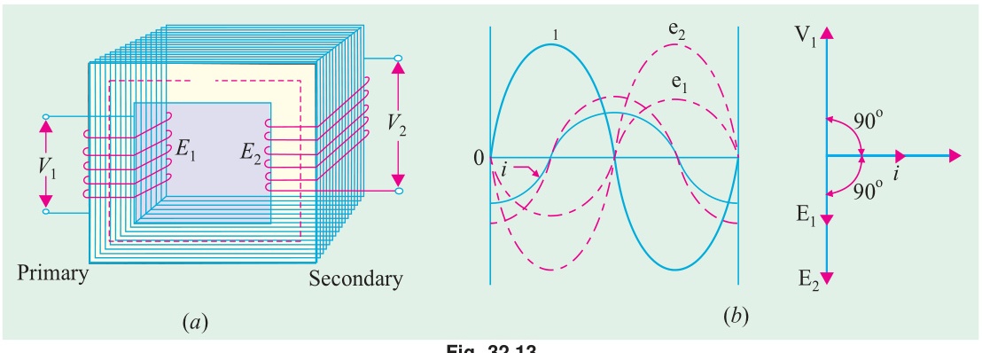
An "ideal transformer" is an idealized mathematical model that isolates the pure electromagnetic transformation mechanism from parasitic non-idealities:
- Zero Winding Resistance (R1=R2=0): Coils are assumed to be wound with hypothetical perfect conductors (zero resistivity). This eliminates all I2R copper losses and internal ohmic voltage drops.
- Zero Leakage Flux (Φl1=Φl2=0): 100% of magnetic flux is confined inside the core, linking every turn of both primary and secondary windings identically. Hence, leakage reactances are zero (X1=X2=0).
- Infinite Core Permeability (μr→∞): The core offers zero magnetic reluctance (R=μAl→0). Therefore, establishing full operating mutual flux Φm requires zero magnetizing ampere-turns: magnetizing current Im=0.
- Zero Core Losses (Ph=0,Pe=0): The core material exhibits zero hysteresis loop area and infinite electrical resistivity (zero eddy currents). The core never heats up (Ic=0).
- Net Consequences: No-load current is zero (I0=0), input power equals output power at all times (η=100%), and voltage regulation is perfect (0%, terminal voltage never drops with load).
Q1(b): Derivation of RMS EMF and EMF-per-Turn Equality
For full derivation see T-01: EMF Equation: E=4.44fNΦm.
- Peak induced EMF: Em=ωNΦm=2πfNΦm.
- RMS value: E=22πfNΦm=2πfNΦm≈4.44fNΦm.
- Why EMF per turn is strictly equal: N1E1=4.44fΦm=N2E2 Because both coils are threaded by the exact same alternating core flux Φ(t), every single loop of copper encircling the core experiences the exact same rate of change of magnetic flux (−dtdΦ). The voltage induced per turn is a fundamental invariant of the magnetic core.
Q1(c): Numerical: 25 kVA, 500/50 Turns, 3000V/50Hz Transformer
Given Data:
- Rating S=25 kVA=25,000 VA
- Primary turns N1=500, Secondary turns N2=50
- Primary voltage V1=3000 V, Frequency f=50 Hz
Step-by-Step Solution:
- Turns Ratio and Secondary EMF: a=N2N1=50500=10 E2=aE1=103000=300 V
- Full-Load Primary and Secondary Currents: I1=V1S=300025,000=8.33 A I2=V2S=30025,000=83.33 A (Notice I2=aI1=10×8.33=83.3 A, perfectly verifying ampere-turn balance N1I1=N2I2).
- Maximum Core Flux (Φm): From E1=4.44fN1Φm: Φm=4.44fN1E1=4.44×50×5003000=111,0003000=0.02703 Wb=27.03 mWb
Question 2
Q2(a): Complete Phasor Diagram of a Practical Transformer
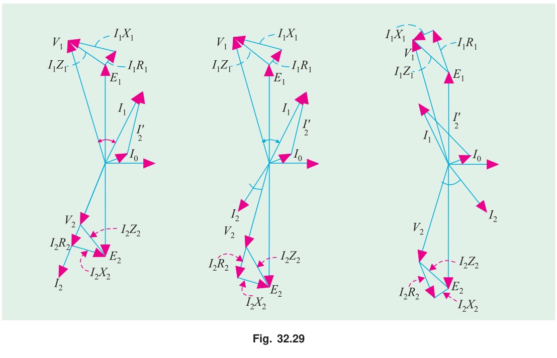
Physical Walkthrough of Phasor Evolution:
- Magnetic Core Reference: Core flux Φm is drawn horizontal (0°).
- Induced EMFs: Both self-induced EMF E1 and mutually induced EMF E2 lag flux by 90° (drawn vertically downward, −90°).
- Secondary Terminal Voltage (V2): When secondary current I2 flows at lagging angle ϕ2, internal winding impedance causes drops. By KVL: E2=V2+I2R2+jI2X2. Graphically, start from the origin, draw V2, add I2R2 parallel to I2, and add jI2X2 leading I2 by 90° to reach E2. Thus V2 is smaller than E2.
- Primary Current (I1):
Total primary current is the phasor sum of two components:
I1=I0+I2′
- I0: No-load excitation current (Ic along −E1, Im along Φm).
- I2′: Primary balancing current (180° opposite to secondary current I2, magnitude KI2).
- Primary Applied Voltage (V1): Applied voltage must overcome both counter-EMF (−E1) and internal primary drops: V1=−E1+I1R1+jI1X1 Draw −E1 vertically upward (+90°), add I1R1 parallel to I1, and add jI1X1 leading I1 by 90°. The closing vector from origin is V1.
Q2(b): No-Load Test: Procedure, Circuit, and Purpose
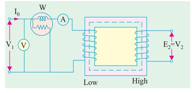
Physical Rationale:
- Why perform on LV side: Safety and convenience. Applying rated 220 V is much safer, easier to regulate with a standard laboratory variac, and meter than several thousand volts on the HV side.
- Why power represents strictly core loss: Secondary winding is open (I2=0). Primary draws only no-load current I0 (typically 2–5% of rated). Primary copper loss is I02R1∝(0.03)2≈0.09% of full-load copper loss—completely negligible! Hence the wattmeter reading W0 captures purely core hysteresis and eddy current dissipation: PFe=W0.
- Extraction of Shunt Parameters: cosϕ0=V0I0W0,Ic=I0cosϕ0,Im=I0sinϕ0 Rc=IcV0,Xm=ImV0
Q2(c): Numerical SC Test and Voltage Regulation Calculation
Given Data:
- Rating: 20 kVA,2400/240 V,50 Hz
- SC test conducted on HV side (2400 V): Vsc=72 V,Wsc=275 W,Isc=I1,rated
Step-by-Step Parameter Extraction:
- Rated HV Current: I1,rated=240020,000=8.333 A
- Series Parameters referred to HV: R01=Isc2Wsc=(8.333)2275=69.44275=3.960Ω Z01=IscVsc=8.33372=8.640Ω X01=Z012−R012=(8.640)2−(3.960)2=74.65−15.68=58.97=7.679Ω
- Voltage Regulation at Full Load, 0.8 PF Lagging (cosϕ=0.8,sinϕ=0.6): ΔV1=I1(R01cosϕ+X01sinϕ)=8.333×(3.960×0.8+7.679×0.6) ΔV1=8.333×(3.168+4.607)=8.333×7.775=64.79 V VR%=V1ΔV1×100%=240064.79×100%=2.70%
Question 3
Q3(a): Limitations of Y-Y Transformers and the Third Harmonic Problem
Why Third Harmonics Exist:
Ferromagnetic cores have non-linear B−H saturation characteristics. To produce a sinusoidal flux wave Φ(t), the required magnetizing current cannot be sinusoidal—it must contain a pronounced 3rd harmonic component (~30–40% of fundamental at 150 Hz).
The Y-Y Trap:
In a 3-phase system, third harmonic currents are zero-sequence: they are completely in phase in all three lines. In an ungrounded 3-wire star (Y-Y) connection, all three line currents must sum to zero at the neutral (ia+ib+ic=0). Since third harmonics want to flow in the same direction simultaneously, they find no return path and are completely blocked!
- Consequence: Since 3rd harmonic magnetizing currents cannot flow, the core flux is forced to become non-sinusoidal (flat-topped).
- A flat-topped flux wave induces sharply peaked EMFs in each phase winding (e=−NdtdΦ). The phase-to-neutral voltages become severely distorted, containing large 3rd harmonic voltage components that overstress winding insulation and produce floating neutral instability.
Engineering Solutions:
- Grounded Neutral (4-Wire System): Provides an external return wire through earth for the zero-sequence 3rd harmonic currents, restoring sinusoidal core flux.
- Tertiary Delta Winding: Adding a small auxiliary delta-connected third winding. The closed delta loop allows 3rd harmonic currents to circulate freely locally, trapping the harmonics inside the transformer and keeping phase voltages pure sine waves.
- Delta-Star (Δ-Y) Connection: The delta primary allows 3rd harmonic currents to circulate freely within the delta loop.
Q3(b): Open-Delta (V-V) Operation When One Transformer is Damaged
For comprehensive capacity and utilization proof see T-04: Open-Delta Connection: Why 57.7% and When to Use It.
- Why it works: By Kirchhoff's Voltage Law, the sum of line voltages in a closed loop is zero: Vab+Vbc+Vca=0. Even when transformer CA is physically removed, the line voltages across the load terminals remain intact: Vca=−(Vab+Vbc). The load continues to receive balanced 3-phase power.
- Capacity: Reduces to 3VI3VI=31=57.7% of original closed-delta bank capacity.
Q3(c): Complete Torque-Speed Characteristic of an Induction Motor
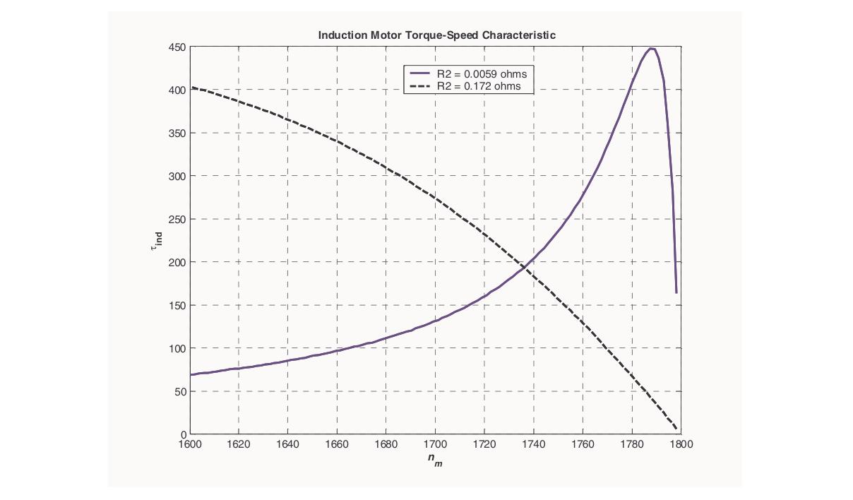
The induction machine operates in three distinct operational regions depending on rotor speed N and slip s=NsNs−N:
- Motoring Region (0<N<Ns, 0<s<1):
Normal operation. Stator field rotates faster than rotor. Electromagnetic torque is positive, dragging the rotor forward in the direction of field rotation.
- At N=0 (s=1): Motor produces starting torque Tst.
- At N=NmT (s=smT=R2/X2): Motor develops breakdown (pull-out) torque Tmax.
- Near synchronous speed (s≈0.02–0.05): Normal operating stable linear zone.
- At synchronous speed N=Ns (s=0): Relative motion ceases ⟹ no induced EMF ⟹ torque drops to zero.
- Generating Region (N>Ns, s<0): Rotor is driven mechanically faster than synchronous speed by an external prime mover (e.g., wind turbine). Slip becomes negative. Induced rotor current reverses direction, creating negative torque that opposes rotation. The machine converts mechanical power into electrical power fed back to the AC grid.
- Plugging / Braking Region (N<0, s>1): Two stator supply leads are swapped while running, suddenly reversing the direction of stator RMF rotation. The rotor is now spinning opposite to the field (N<0⟹s=NsNs−(−N)>1). The machine develops strong counter-torque that rapidly decelerates the rotor to a dead stop (used for rapid emergency braking).
Question 4
Q4(a): Conditions for Parallel Operation of 3-Phase Transformers
Connecting two 3-phase transformers in parallel requires strict adherence to five fundamental rules:
- Identical Voltage Ratios: Prevents continuous circulating currents between transformers at no load.
- Identical Polarity: Prevents dead short-circuits.
- Same Phase Sequence: Reversing phase sequence (e.g., A-B-C vs A-C-B) creates line-to-line short circuits with full line voltage across pairs of terminals.
- Zero Relative Phase Displacement (Same Vector Group): Both units must belong to compatible clock groups (e.g., both Dyn11 or both Yyn0). A 30° phase shift between secondary line voltages causes massive circulating currents driven by ΔV=2Vsin(15°)≈0.52Vrated.
- Equal Per-Unit Impedances (Zpu): Ensures that external load divides strictly in proportion to their kVA ratings without overloading either unit.
Q4(b): Physical Methods for Generating Magnetic Fields
- Permanent Magnets: Arise from uncancelled microscopic electron spins and orbital angular momenta in ferromagnetic materials (NdFeB, Alnico) aligned within magnetic domains. Produces constant DC flux with zero power dissipation.
- DC Electromagnets: DC current flowing through wire coils generates steady magnetic fields via Ampere's Law (∇×H=J). Used in DC machine stator poles and synchronous rotor exciters.
- Pulsating AC Electromagnets: Single-phase alternating current through a coil sets up a field whose magnitude oscillates sinusoidally along a fixed spatial axis. Used in transformer cores.
- Rotating Magnetic Field (Polyphase Stator): Balanced polyphase AC currents distributed in spatial windings create a smoothly revolving field of constant amplitude. Three-phase windings yield 1.5Φm rotating at synchronous speed, forming the operating foundation of all AC induction and synchronous motors.
Q4(c): Speed Control of Slip-Ring IM by Adding Rotor Resistance
Given Data:
- Poles P=4, Frequency f=50 Hz⟹Ns=4120×50=1500 rpm
- Rotor resistance R2=0.30Ω/phase
- Initial operating point: N1=1440 rpm⟹s1=15001500−1440=0.04
- Target operating point: N2=1320 rpm⟹s2=15001500−1320=0.12
- Condition: Load torque remains strictly constant (T1=T2).
Physical Principle and Solution:
In the normal operating stable zone (small slip), rotor leakage reactance is negligible compared to rotor resistance (sX2≪R2). The torque equation simplifies to: T≈RtotalksE22 For constant torque at constant applied voltage: R2s1=R2+Rexts2 0.300.04=0.30+Rext0.12 0.30+Rext=0.040.12×0.30=3×0.30=0.90Ω Rext=0.90−0.30=0.60Ω/phase
Physical Insight: To develop the same electromagnetic torque at a lower speed (higher slip), the rotor current must be maintained at its original value. Since induced rotor EMF increases proportionally with slip (E2s=sE2), total rotor circuit resistance must be increased in the exact same proportion to keep I2≈RtotalsE2 constant.
SECTION - B (Induction Motors: Q5 to Q8)
Question 5
Q5(a): Definitions of Synchronous Speed, Slip, and Slip Speed
- Synchronous Speed (Ns): The rotational speed of the magnetic field produced by the balanced 3-phase stator currents inside the air gap. It depends solely on supply frequency f and stator pole pairs P: Ns=P120f rpm,ωs=P4πf rad/s
- Slip Speed (Nslip): The relative physical speed between the rotating magnetic field and the actual mechanical rotor: Nslip=Ns−N rpm Physical Meaning: This relative motion is what causes the rotor bars to cut magnetic flux lines, inducing voltage and current by Faraday's Law. Without slip speed, induced rotor voltage would be zero.
- Slip (s): The normalized fractional ratio of slip speed to synchronous speed:
s=NsNs−N
- Standstill: N=0⟹s=1.0.
- Synchronous speed: N=Ns⟹s=0.
- Normal full-load motoring: s≈0.02 to 0.05.
Q5(b): Starting Torque Derivation and Maximum Starting Torque Condition
Starting torque is obtained by evaluating the torque equation at standstill (s=1): Tst=R22+(1)2X22k(1)E22R2=R22+X22kE22R2 To find the rotor resistance that maximizes starting torque, differentiate Tst with respect to R2 and set to zero: dR2dTst=kE22[(R22+X22)2(R22+X22)(1)−R2(2R2)]=0 R22+X22−2R22=0⟹R22=X22⟹R2=X2
Substituting R2=X2 into the starting torque expression: Tst,max=X22+X22kE22X2=2X2kE22 Notice that Tst,max equals the absolute maximum running breakdown torque Tmax! In slip-ring (wound-rotor) induction motors, external resistance is inserted so that total rotor resistance equals standstill reactance (R2+Rext=X2), allowing the motor to start with maximum possible torque while drawing minimal starting current.
Q5(c): Rotating Magnetic Field Produced by a 2-Phase Supply
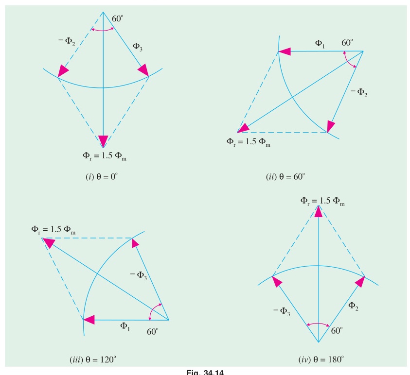
Setup:
Consider two stator windings placed 90° apart in space (Phase A along X-axis, Phase B along Y-axis), energized by balanced 2-phase currents 90° apart in time: ia(t)=Imsinωt,ib(t)=Imsin(ωt−90°)=−Imcosωt
Spatial Flux Components:
- Flux along X-axis: Φx=Φmsinωt
- Flux along Y-axis: Φy=−Φmcosωt
Resultant Vector:
- Magnitude: Φr=Φx2+Φy2=Φm2sin2ωt+Φm2cos2ωt=Φm=constant
- Spatial Angle: θ=tan−1(ΦxΦy)=tan−1(sinωt−cosωt)=ωt−90° dtdθ=ω=2πf⟹Ns=P120f rpm
Comparison with 3-Phase:
- 2-Phase produces constant flux magnitude of Φm.
- 3-Phase produces constant flux magnitude of 1.5Φm (50% larger flux from the same peak phase flux).
Question 6
Q6(a): Effect of Supply Frequency Increase on Torque and Speed
When supply frequency jumps from f1 to f2>f1 with terminal voltage V held constant:
- Synchronous Speed: Ns=P120f increases in direct proportion to f.
- Magnetic Flux Attenuation: Core flux is Φm∝fV. With V constant and f higher, core flux weakens significantly.
- Leakage Reactance: Standstill reactance X2=2πfL2 increases proportionally with f.
- Catastrophic Drop in Breakdown Torque: Tmax=2X2kE22∝ωs12(2πfL2)(V/f)2∝f3V2 Maximum torque collapses inversely with the cube of frequency (1/f3)! A 20% frequency increase slashes maximum torque capability by over 42%.
- Why V/f Control is Mandatory: To vary motor speed without sacrificing torque capability, variable frequency drives always adjust voltage and frequency simultaneously such that the ratio V/f remains strictly constant.
Q6(b): Increase in Copper Loss when Line Voltage Drops to 90%
Given:
- Motor drives a constant-torque load (T=constant, independent of speed).
- Terminal voltage drops to V2=0.9V1.
Physical Analysis:
In the normal low-slip operating range, torque is proportional to slip and voltage squared: T≈KR2sV2 Since the load demands the exact same torque T: s1V12=s2V22⟹s2=s1(V2V1)2=s1(0.91)2=0.81s1≈1.2346s1 Operating slip must increase by 23.46% to compensate for the weaker magnetic field.
Now consider rotor copper loss: Pr,Cu=sPg Because load torque T and synchronous speed ωs are constant, air-gap power Pg=Tωs remains constant. Therefore, rotor copper loss is directly proportional to slip: PCu,oldPCu,new=s1s2=1.2346 Percentage Increase in Cu Loss=(1.2346−1)×100%=23.46%
Physical Warning: Operating an induction motor under undervoltage conditions causes it to draw substantially higher current and generate 23.5% more heat in its windings, frequently tripping thermal overload relays.
Q6(c): Rotor Efficiency Derivation
- Air gap input power: Pg=3I22sR2
- Rotor ohmic loss: Pr,Cu=3I22R2=sPg
- Developed mechanical power: Pm=Pg−Pr,Cu=(1−s)Pg
- Rotor efficiency: ηrotor=PgPm=Pg(1−s)Pg=1−s
Question 7
Q7(a): Double-Field Revolving Theory of 1-Phase IM
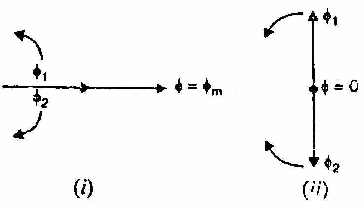
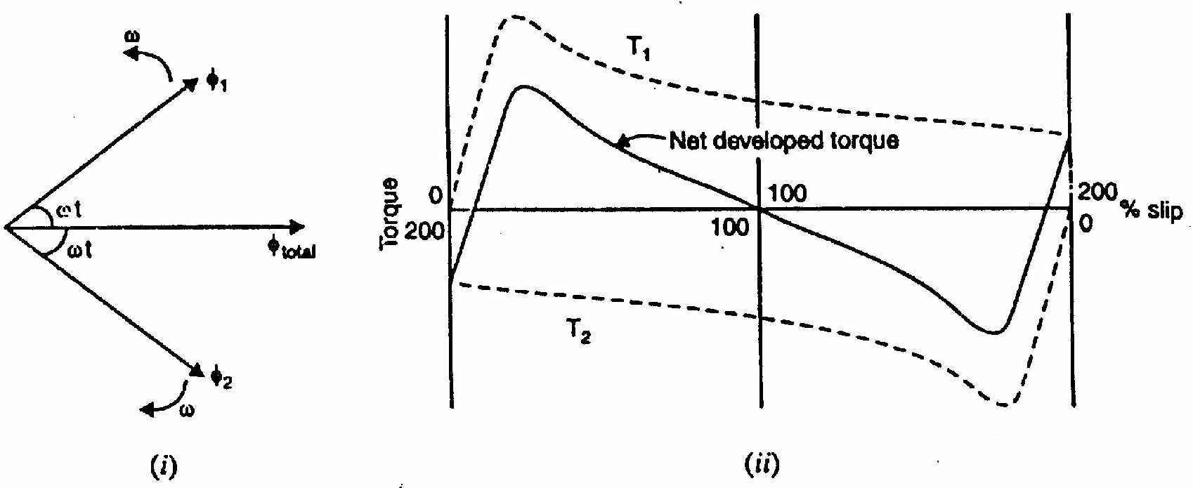
See full details in IM-03: Single-Phase Induction Motor: Double Revolving Field Theory.
- Forward field rotates at +Ns with slip sf=s.
- Backward field rotates at −Ns with slip sb=2−s.
- At standstill (s=1), forward torque equals backward torque (Tf=Tb), yielding zero net starting torque.
Q7(b): Operation of Capacitor-Start-and-Run (Two-Value) Induction Motor
- Starting: Large electrolytic capacitor (Cst) in parallel with run capacitor (Crun) forces auxiliary current to lead main current by 90°, producing a balanced two-phase rotating field with high starting torque (200–350% FL).
- Running: Centrifugal switch disconnects Cst at 75% speed. Small AC continuous-duty capacitor (Crun) remains in series with auxiliary winding, maintaining a clean rotating field under running conditions. This maximizes efficiency, achieves near-unity power factor (0.95), and eliminates acoustic vibration.
Q7(c): Calculation of Starting Capacitor for Quadrature Current
Given Data:
- Supply: 230 V,50 Hz
- Main winding impedance: Zm=4.5+j3.7Ω
- Auxiliary winding impedance: Za=9.5+j3.5Ω
Condition for Quadrature Currents:
Auxiliary current Ia must lead main winding current Im by exactly 90° in time:
- Main Winding Phase Angle: ϕm=tan−1(RmXm)=tan−1(4.53.7)=tan−1(0.8222)=39.43° lagging
- Required Auxiliary Branch Phase Angle: For Ia to lead Im by 90°, Ia must lead the terminal voltage by: ϕa=90°−ϕm=90°−39.43°=50.57° leading
- Net Auxiliary Reactance with Series Capacitor XC: Total auxiliary branch impedance is Ztotal,a=Ra+j(Xa−XC)=9.5−j(XC−3.5). For the branch to have a leading angle of 50.57°: tan(50.57°)=RaXC−Xa=9.5XC−3.5 tan(50.57°)=1.2160 XC−3.5=1.2160×9.5=11.552Ω XC=11.552+3.5=15.052Ω
- Capacitance Value: C=2πfXC1=2π×50×15.0521=4728.71=2.1147×10⁻⁴ F=211.5μF
Question 8
Q8(a): Synchronous Watt Definition and Practical Meaning
Definition:
A synchronous watt is a convenient unit of torque used in AC motor analysis. It is defined as the torque which, at synchronous speed, develops one watt of mechanical power: T (in synchronous watts)=Pg (air-gap power in watts)
Physical Meaning:
Electromagnetic torque in mechanical units (N-m) is: T=ωsPg=602πNsPg Since synchronous speed ωs is constant for a given motor, torque is directly proportional to air-gap power Pg. Expressing torque directly in "synchronous watts" saves engineers from repeatedly multiplying and dividing by 602πNs in induction motor power flow and circle diagram calculations.
Example: If a 4-pole, 50 Hz motor (Ns=1500 rpm⟹ωs=157.08 rad/s) has an air-gap power of Pg=5000 W:
- Torque in synchronous watts =5000 sync watts.
- Torque in conventional SI units =157.085000=31.83 N-m.
Q8(b): Meaning of Vector Group and "Dyn5" Representation
What Vector Group Tells an Engineer:
- Primary Winding Connection: Uppercase letter (D = Delta, Y = Star).
- Secondary Winding Connection: Lowercase letter (d = Delta, y = Star).
- Neutral Conductor Availability: Letter 'n' indicates neutral is brought out.
- Phase Displacement (Clock Position): An integer 0–11 indicating the angular phase displacement of secondary line voltage relative to primary line voltage. Each clock hour represents 30° lagging (12 o'clock = 0°, 1 o'clock = 30° lag, 5 o'clock = 150° lag).
Physical Decoding of "Dyn5":
- D: Primary winding is connected in Delta.
- y: Secondary winding is connected in Star.
- n: Secondary neutral terminal is brought out externally for 4-wire supply.
- 5: Secondary line voltage lags primary line voltage by 5×30°=150° (pointing to 5 o'clock on the phasor dial).
Q8(c): Induction Motor Circle Diagram Analysis
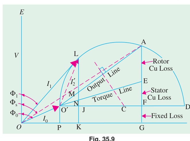
First-Principles Theory of the Circle Diagram:
As the mechanical load on an induction motor varies from no-load to standstill, the equivalent circuit impedance traces a circular locus in the complex current plane (Heyland circle).
- Data Required:
- No-Load Test (V0,I0,cosϕ0): Defines the origin O′ of the circle locus.
- Blocked-Rotor / SC Test scaled to rated voltage (Isc,cosϕsc): Defines the short-circuit point S.
- Stator Resistance R1: Splits the vertical line representing standstill losses into stator copper loss and rotor copper loss.
- Graphical Extraction at Rated Output (14.92 kW):
- Vertical distance from the output line represents mechanical power output.
- At the point corresponding to 14.92 kW, reading the vector from origin O to that operating point yields:
- Line Current I1: Length of the phasor vector ≈30 A.
- Operating Power Factor cosϕ1: Cosine of the angle between voltage axis and current phasor ≈0.76 lagging.
- Slip s: Ratio of vertical intercept of rotor Cu loss to air-gap power ≈5%.
- Efficiency η: Ratio of output power to total input power ≈84%.
- Maximum Torque: Maximum vertical distance from the circle circumference to the torque line.
Source: PrevYearQuestions/2021.md