answers_exam_style/2019_answer.md
23.4 KB · commit d2f3b6e
← 2018 Answer | 🏠 Index | 2020 Answer →
ECE 2207: 2019 Semester Final: Exam Style Answers
RUET · ECE Dept · 2nd Year Odd Semester 2019 Full Marks: 72 · Time: 3 Hours · Attempt any 6 (3 from each section)
SECTION - A (Transformers: Q1 to Q4)
Question 1
(a) Define transformer. How is energy transferred from primary to secondary? Distinguish primary and secondary windings. [04]
Transformer: A static electromagnetic device that transfers electrical energy between two or more circuits through mutual electromagnetic induction, at the same frequency but different voltage and current levels.
Energy transfer mechanism: AC voltage applied to the primary winding drives a current that creates an alternating magnetic flux in the iron core. By Faraday's Law, this alternating flux induces an EMF in the secondary winding. If a load is connected, current flows and energy is delivered to the load.
| Feature | Primary Winding | Secondary Winding |
|---|---|---|
| Connection | Connected to AC supply | Connected to load |
| Role | Receives electrical energy | Delivers electrical energy |
| Voltage | Usually higher (step-down) or lower (step-up) | Determined by turns ratio |
| Symbol | V1, I1, N1 | V2, I2, N2 |
(b) Derive the expression for EMF induced in a transformer winding. Show EMF per turn is same in both. [04]
Let core flux: Φ(t)=Φmsinωt
By Faraday's Law, primary induced EMF: e1=−N1dtdΦ=−N1ωΦmcosωt=N1ωΦmsin(ωt−90°)
Peak value: Em1=N1ωΦm=2πfN1Φm
RMS: E1=4.44fN1Φm
Similarly: E2=4.44fN2Φm
EMF per turn: N1E1=4.44fΦm=N2E2
EMF per turn is 4.44fΦm for both windings. Same for primary and secondary. (Proved)
(c) Why does current flow in primary when secondary is open? Explain how primary current increases as secondary load increases. [04]
Why current flows at no-load: When V1 is applied, the primary winding behaves as a coil with resistance R1 and inductance L1. To set up the alternating core flux Φm (which induces E1≈V1 to balance applied voltage), a small magnetizing current Im must flow. Also, a small active component Ic flows to supply core losses (hysteresis + eddy). Together: I0=Ic2+Im2≈2-10% of rated current
How primary current increases with secondary load: When a load is connected and secondary current I2 flows, it creates a demagnetizing MMF =N2I2. This tends to reduce the core flux. But E1≈V1 (supply voltage is fixed), so the flux must stay essentially constant. To maintain the flux, the primary must draw additional current I2′=I2×N2/N1. Total primary current: I1=I0+I2′=I0+N1N2I2
As load current I2 increases, I1 increases proportionally.
Question 2
(a) Discuss OC and SC tests of a single-phase transformer. [03]
Open-Circuit (OC) test:
- Performed on the low-voltage (LV) side with the high-voltage (HV) side open.
- Rated voltage is applied to the LV side.
- Voltmeter (V0), ammeter (I0), wattmeter (W0) readings are taken.
- All power input W0 = core (iron) loss, since winding current is very small.
- Determines: core loss PFe=W0, magnetizing reactance Xm, core loss resistance Rc.
- Core loss is constant for all loads.
Short-Circuit (SC) test:
- Performed on the HV side with the LV side short-circuited.
- Reduced voltage applied until rated current flows.
- Voltmeter (Vsc), ammeter (Isc), wattmeter (Wsc) readings are taken.
- Core losses are negligible at low voltage. Wsc = full-load copper loss.
- Determines: equivalent resistance R01, equivalent reactance X01, leakage impedance Z01.
(b) Define voltage regulation. Find VR for unity, lagging, and leading pf. [04]
Voltage regulation (VR): The change in secondary terminal voltage from no-load to full-load as a percentage of rated full-load voltage, with primary voltage held constant.
VR%=V2,FLV2,NL−V2,FL×100%
Using the approximate formula (per-unit or percentage):
Unity pf (cosϕ=1, sinϕ=0): VR%≈ϵr=V2I2(R01cosϕ+X01sinϕ)×100=V2I2R01×100
Lagging pf (cosϕ lag): VR%=V2I2(R01cosϕ+X01sinϕ)×100(positive, larger than unity pf)
Leading pf (cosϕ lead): VR%=V2I2(R01cosϕ−X01sinϕ)×100(can be negative: voltage rises with leading load)
(c) 10 kVA, 2200/220V, 60 Hz. OC (high side open): 220V, 1.5A, 153W. SC (low side shorted): 115V, rated I, 224W. Find half-load and full-load efficiencies at upf and 0.8 pf lag. [05]
Core loss: PFe=153 W
Rated current (primary, HV side): I1=10000/2200=4.545 A
Full-load Cu loss: PCu,FL=224 W
Full load efficiency:
At upf: η=10000+153+22410000=1037710000=96.37%
At 0.8 pf: η=8000+153+2248000=83778000=95.50%
Half-load efficiency: Cu loss =(0.5)2×224=56 W
At upf: η=5000+153+565000=52095000=95.99%
At 0.8 pf: η=4000+153+564000=42094000=95.03%
Question 3
(a) What is transformer breathing? Show max efficiency when core loss = copper loss. [04]
Transformer breathing: As the transformer load varies, its temperature changes. Cooling oil expands when hot and contracts when cool. In conservator-type transformers, oil level rises and falls in the conservator tank. Air is drawn in and expelled through a silica gel breather (to remove moisture). This process of inhaling/exhaling air is called transformer breathing. Moisture absorption by the insulating oil degrades it over time, which is why the breather desiccant must be regularly replaced.
Max efficiency proof:
Efficiency: η=x⋅S⋅cosϕ+PFe+x2PCu,FLx⋅S⋅cosϕ
where x = fraction of full load. Differentiate w.r.t. x and set to zero:
dxdη=0⟹x2PCu,FL=PFe
Cu loss=Fe (core) lossat maximum efficiency
The load fraction at max efficiency: x=PFe/PCu,FL
(b) "A considerable economy is achieved in core material if the middle phase winding of a 3-phase shell-type transformer is wound in the reverse direction." Justify. [04]
In a 3-phase shell-type transformer, three single-phase cores are placed side by side. The flux in the middle limb is the vector sum of the fluxes from the two outer limbs.
For a balanced 3-phase system: ΦA+ΦB+ΦC=0 at every instant.
If the middle phase (B) is wound in the same direction as A and C: the middle yoke carries the flux from both A and C passing through it. The cross-section must be larger.
If the middle phase (B) is wound in the reverse direction: effectively ΦB is now −ΦB, which equals ΦA+ΦC. The flux in the middle limb equals the sum of A and C (with appropriate sign), meaning the yoke cross-section can be reduced because the net flux sharing is more symmetric and the yokes carry only the flux from adjacent limbs.
Economy: The two outer yokes carry only the flux from one outer phase each. Only the middle limb must carry the combined flux. With reverse winding, the mutual cancellation reduces peak yoke flux. Less core material is needed for the same performance.
(c) Yd11 in parallel with Dy1: possible? [04]
Vector group numbers: Each unit represents a 30° phase shift (clock notation: 12 = 0°, 11 = 330° = −30°, 1 = 30°).
- Yd11: Phase displacement = 11 × 30° = 330° (= −30°): secondary lags primary by 30°.
- Dy1: Phase displacement = 1 × 30° = 30°: secondary leads primary by 30°.
The difference in secondary voltage phase angles: 330°−30°=300° (or equivalently 60° lag). This is a 60° phase displacement between their secondary voltages.
Two transformers can only be paralleled if their secondary voltages are exactly in phase (same vector group number). A 60° difference means a large circulating current would flow even at no load.
Direct parallel: not possible due to the 60° phase displacement.
Possible workaround: Yes, it is possible if a phase-shifting transformer or external connection rearrangement shifts one transformer's output by 60° to match the other. In practice, rearranging the external secondary connections (changing the bus-bar connections) can sometimes compensate for a 30° difference: but a 60° difference is generally not bridgeable by simple reconnection.
Conclusion: Direct parallel operation is not possible without modification.
Question 4
(a) Define single phasing of a 3-phase Δ-Δ transformer. Show secondary voltages remain balanced when one phase is damaged. [04]
Single phasing of a 3-phase transformer: One of the three single-phase units in the bank fails or is disconnected. The remaining two units continue to supply the 3-phase load.
For a Δ-Δ transformer with one phase damaged:
Let transformers T_AB, T_BC, T_CA form the bank. If T_CA fails, we have open-Δ (T_AB and T_BC remain).
In the primary Δ: voltage VCA=VAB+VBC (by Kirchhoff's voltage law around the delta loop, even with T_CA removed, the primary line voltages are fixed by the 3-phase supply). So VAB and VBC are determined by supply. VCA=−(VAB+VBC): the voltage still exists across the open terminals.
On the secondary side: Vab=K⋅VAB, Vbc=K⋅VBC. Since supply is balanced, VAB and VBC are balanced. The open secondary terminal for phase CA maintains voltage Vca=K⋅VCA (because the delta loop closes through the other two transformer EMFs).
Result: All three secondary line voltages remain balanced at the rated value, even with one transformer removed. (Shown)
Trade-off: Only 57.7% of the original bank's kVA capacity remains available.
(b) Convert 3-phase to 2-phase or vice versa? If yes, explain. [04]
Yes. This is done using the Scott (T-T) connection.
Principle: Two single-phase transformers are used.
-
Main transformer: Primary connected between two phases of the 3-phase supply (e.g., lines A and B). Secondary provides one phase of the 2-phase output.
-
Teaser transformer: Primary connected from the mid-point of the main transformer primary to the third line (C). The teaser primary has 3/2 (86.6%) of the main transformer's turns. Secondary provides the second phase of the 2-phase output, exactly 90° displaced from the first.
Why it works: The two primary voltages are 90° apart geometrically in the phasor diagram (the line-to-midpoint voltage is perpendicular to the line-to-line voltage in a balanced 3-phase system). This 90° separation transfers to the two secondary voltages, giving a balanced 2-phase output.
Reverse (2-phase to 3-phase): Connect the two-phase supply to the secondaries and the 3-phase supply comes from the primaries: the same transformation works in reverse because transformers are reciprocal devices.
(c) 100 kVA transformer, full-load loss = 6 kW, half iron and half copper. Full load for 3 hr, half load for 4 hr. Find commercial efficiency. [04]
Given: Total full-load loss =6 kW → PFe=3 kW, PCu,FL=3 kW (equal split)
Energy output:
| Period | Load | Hours | kWh |
|---|---|---|---|
| Full load | 100 kW | 3 | 300 |
| Half load | 50 kW | 4 | 200 |
| Remaining (no load) | 0 | 17 | 0 |
| Total | 24 | 500 kWh |
Iron loss energy (24 hours): 3×24=72 kWh
Copper loss energy:
| Period | Cu loss | Hours | kWh |
|---|---|---|---|
| Full load | 3000 W | 3 | 9.0 |
| Half load | (0.5)2×3000=750 W | 4 | 3.0 |
| No load | 0 | 17 | 0 |
| Total Cu | 12 kWh |
Total losses =72+12=84 kWh
Total input =500+84=584 kWh
ηcommercial=584500×100=85.62%
SECTION - B (Induction Motors: Q5 to Q8)
Question 5
(a) What is an electrical machine? Describe the principle of operation of a 3-φ induction motor. [04]
Electrical machine: A device that converts electrical energy to mechanical energy (motor) or mechanical energy to electrical energy (generator), using the principles of electromagnetic induction.
3-φ IM operating principle:
- Three-phase balanced AC supply to stator creates a RMF of magnitude 1.5Φm at synchronous speed Ns=120f/P rpm.
- The RMF sweeps across stationary rotor bars. Relative motion induces EMF in rotor bars (Faraday's Law).
- Induced EMF drives rotor current through short-circuited rotor bars.
- Rotor current in the stator field produces Lorentz force (torque).
- Rotor spins in the direction of RMF (Lenz's Law: to reduce relative motion).
- Motor always runs at N<Ns (slip s>0), otherwise torque = 0.
(b) Why is an IM called a rotating transformer? Advantages and disadvantages. [04]
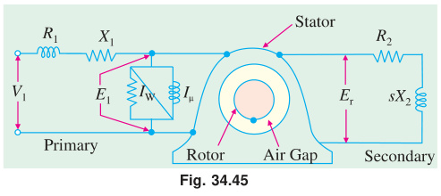
Rotating transformer analogy:
| Aspect | Transformer | Induction Motor |
|---|---|---|
| Primary | Primary winding (stator) | Stator winding |
| Secondary | Secondary winding (rotor) | Rotor bars |
| Power transfer | Via mutual flux in core | Via rotating field in air gap |
| Secondary | Fixed (static) | Rotating |
| Secondary current | Load current | Rotor current (produces torque) |
The IM is called a rotating transformer because power transfers from stator to rotor by electromagnetic induction, just like in a transformer. The main difference: the rotor rotates.
Advantages:
- Simple, strong construction (no commutator, no brushes in squirrel-cage type)
- Self-starting
- Low maintenance and long life
- Can be used in hazardous environments (totally enclosed)
- Wide speed and size range available
Disadvantages:
- Speed control is difficult and costly
- Poor power factor at light loads (draws reactive current)
- Starting current is high (6–8 times rated)
- Speed drops with load (not constant-speed like synchronous motor)
(c) 4-pole, 50 Hz IM. Find: (i) synchronous speed, (ii) rotor speed at s = 4%, (iii) rotor frequency at 600 rpm. [04]
Given: P=4, f=50 Hz
(i) Synchronous speed: Ns=4120×50=1500 rpm
(ii) Rotor speed at s=4%: N=Ns(1−s)=1500(1−0.04)=1500×0.96=1440 rpm
(iii) Rotor frequency at N=600 rpm: s=NsNs−N=15001500−600=1500900=0.6
fr=sf=0.6×50=30 Hz
Question 6
(a) 415V, 29.84 kW, 50 Hz delta-connected motor. No-load: 415V, 21A, 1250W. Locked rotor: 100V, 45A, 2730W. Circle diagram: line current, pf at rated output, max torque. [08]
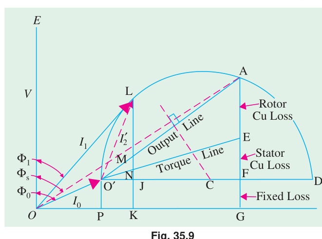
No-load point (referred to line values): cosϕ0=3VLI0W0=3×415×211250=150921250=0.0828,ϕ0=85.25°
No-load components: I0x=21×0.0828=1.74 A (active) I0y=21×sin(85.25°)=21×0.9966=20.93 A (reactive)
Short-circuit point (at full voltage): Isc=45×100415=186.75 A
cosϕsc=3×Vsc×Isc,testWsc=3×100×452730=77942730=0.3503,ϕsc=69.5°
Iscx=186.75×0.3503=65.44 A Iscy=186.75×sin(69.5°)=186.75×0.9367=174.94 A
Diameter of circle:
The short-circuit current Isc defines the diameter. The no-load current I0 defines the no-load point.
Stator and rotor copper loss line: Stator and rotor Cu losses are equal at standstill (given). So the torque line bisects the vertical intercept at the SC point.
From circle diagram at rated output (29.84 kW):
Input power at rated output (using circle diagram reading): Output kW line drawn at height corresponding to 29.84 kW.
(i) Line current at rated output: ≈ 58 A (read from circle diagram)
(ii) Power factor at rated output: ≈ 0.71 lagging
(iii) Maximum torque (from circle diagram):
Maximum torque corresponds to the longest vertical intercept between the upper semi-circle and the torque line.
Tmax≈2πNs3×415×Imax torque≈read from diagram
(b) Prove: Xc=Xa+Zm+Xmrarm for a capacitor split-phase motor. [04]
For maximum starting torque, Im and Ia must be 90° apart.
Taking main winding current as reference:
- Main winding: Zm=rm+jXm, so Im=V/Zm (lagging by ϕm)
- Auxiliary winding + capacitor: Za=ra+j(Xa−Xc), so Ia leads or lags depending on Xc
For 90° between Im and Ia: the imaginary part of Za must satisfy a specific condition.
Using phasor geometry, when the angle between Im and Ia=90°: Xc=Xa+Xm+Zmrarm
(Derivation requires equating the phase angle condition from the phasor diagram.)
Question 7
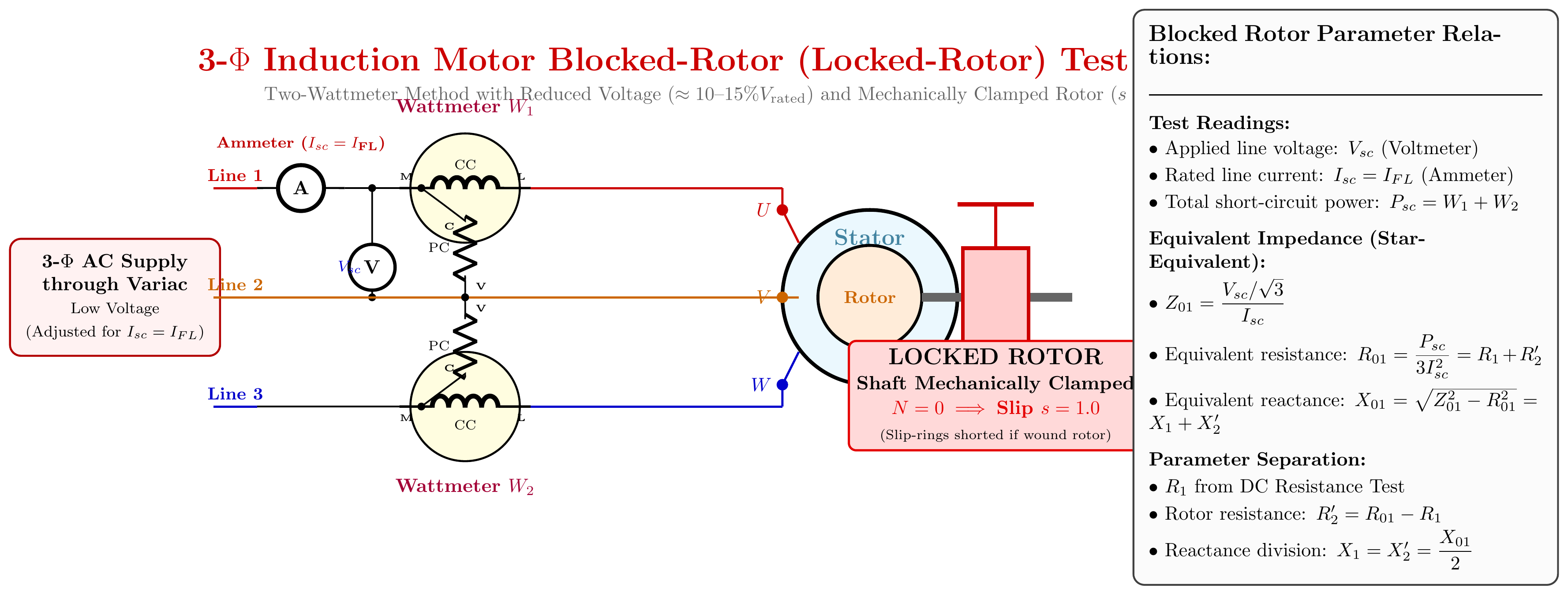
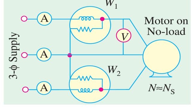
(a) Define plugging. Describe blocked rotor test and no-load test. [04]
Plugging: A braking method for induction motors. The phase sequence of the stator supply is reversed while the motor is running. The stator field now rotates opposite to the rotor. The motor develops a torque opposing motion. The motor decelerates rapidly. Supply is cut before the motor reverses.
Blocked rotor test: Rotor locked (N=0, s=1). Reduced voltage applied until rated current flows. Measure Vsc, Isc, Psc. Determines: R01=Psc/(3Isc2), Z01=Vsc/(3Isc), X01=Z012−R012. Gives copper losses and equivalent circuit series parameters.
No-load test: Motor runs at no-load (no shaft load). Rated voltage applied. Measure V0, I0, P0. The no-load power P0 = stator iron loss + friction and windage loss + small stator copper loss. Determines shunt branch parameters (Rc, Xm) and friction/windage losses.
(b) Effects of direct-line starting of IM > 25 kW. How to minimize? [04]
Effects of direct-on-line (DOL) starting:
- Starting current surge =5–8 times rated current. This causes voltage dips in the supply that affect other loads.
- High mechanical stress on motor shaft, couplings, and driven equipment due to high starting torque surges.
- Thermal stress on windings: repeated DOL starting can overheat the motor.
- For motors > 25 kW, the utility supply authority often prohibits DOL starting due to supply disturbances.
How to minimize:
- Star-delta starter: Reduces starting voltage to VL/3. Starting current and torque reduce to 1/3 of DOL values.
- Auto-transformer starter: Reduced voltage via tapped autotransformer. Provides better torque-current ratio than Y-Δ.
- Rotor resistance (slip-ring motor): Insert external resistance in rotor circuit to improve starting torque with reduced current.
- Soft starter (electronic): Thyristor-based gradual voltage ramp-up. Smooth starting, no current surge.
- Variable frequency drive (VFD): Controls both voltage and frequency. Best control, most expensive.
(c) Define braking of IM. How can speed be controlled? [04]
Braking of IM: Applying a decelerating torque to bring the motor to rest (or to control speed during deceleration). Three methods: plugging, dynamic braking, regenerative braking.
Speed control methods:
-
Stator voltage control: Reduce supply voltage → reduce torque → speed drops. Simple but poor efficiency. Used for fan/pump loads.
-
Supply frequency control (V/f control): Change both V and f proportionally. Synchronous speed Ns=120f/P changes. Wide, smooth speed range. Used in VFDs.
-
Pole changing: Switch between winding configurations to change the number of poles (P). Gives discrete speed steps (Ns=120f/P). Only for squirrel-cage motors.
-
Rotor resistance control: Add external resistance in rotor (slip-ring motors). Higher slip = lower speed. Simple but lossy.
-
Slip energy recovery: Feed slip power back to supply (Kramer system) instead of dissipating. Efficient but complex.
Question 8
(a) What is pull-out torque? Derive the equation for maximum starting torque of a 3-φ IM. [05]
Pull-out torque: The maximum torque a 3-phase IM can develop while running. Also called breakdown torque or Tmax. If the mechanical load torque exceeds pull-out torque, the motor stalls.
Maximum starting torque derivation:
Starting torque is the torque at s=1 (standstill): Tst=R22+X22kE22R2
To find R2 for maximum starting torque, differentiate w.r.t. R2 and set to zero: dR2dTst=(R22+X22)2(R22+X22)−R2(2R2)=0
R22+X22−2R22=0⟹R2=X2
For maximum starting torque, rotor resistance must equal standstill rotor reactance.
Substituting R2=X2: Tst,max=X22+X22kE22X2=2X2kE22
Note: Tst,max=Tmax (when R2=X2, starting torque equals the maximum running torque). (Derived)
(b) Explain why a 1-φ IM is not self-starting using double field revolving theory. [03]
A single-phase stator creates a pulsating flux, not rotating. By the double-field revolving theory, this pulsating flux resolves into:
- Forward RMF: magnitude Φm/2, speed +Ns
- Backward RMF: magnitude Φm/2, speed −Ns
At standstill (s=1 for forward, s=2−1=1 effective for backward):
- Forward torque Tf = backward torque Tb (both equal and opposite)
- Net torque =Tf−Tb=0
So the single-phase IM develops no net starting torque and cannot start by itself.
(c) 8-pole, 50 Hz IM. sFL=2%, R2=0.001Ω, X2=0.005Ω. Find: (i) Tmax/TFL ratio, (ii) speed at max torque. [04]
Ns=8120×50=750 rpm
smT=X2R2=0.0050.001=0.2
Using a=smT=0.2, sf=0.02: TmaxTf=a2+sf22asf=0.04+0.00042×0.2×0.02=0.04040.008=0.1980
TfTmax=0.19801=5.05
Speed at max torque: NmT=750(1−0.2)=600 rpm
Source: PrevYearQuestions/2019.md