SlidesByMaam/L-11_ECE-2107.md
16.1 KB · commit d2f3b6e
Electrical Machines-I
ECE-2107
Transforer-SL4
Fariya Tabassum
Assistant Professor, Dept. of Electrical & Computer Engineering
Rajshahi University of Engineering & Technology, Rajshahi-6204
“Say, “Have you considered: if your water was to become sunken [into the earth], then who could bring you flowing water””.
[Sura al-Mulk]
Three-phase transformers
Necessity of three-phase transformers
Almost all the major power generation and distribution systems in the world today are three-phase ac systems.
Three-phase transformers
Transformers for three-phase circuits can be constructed in two ways.
- One approach is simply to take three single-phase transformers and connect them in a three-phase bank.
- An alternative approach is to make a three-phase transformer consisting of three sets of windings wrapped on a common core.
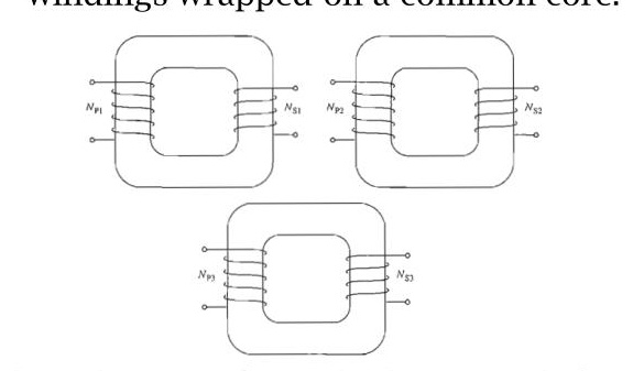 A three phase transformer bank composed of independent transformers
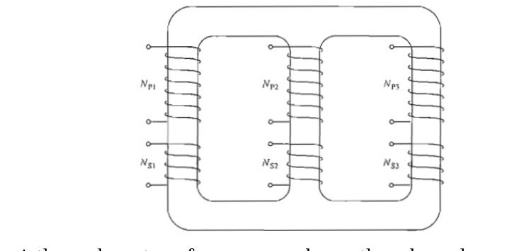 A three phase transformer wound on a three-legged core
Three-phase transformers
- A single three-phase transformer is lighter, smaller, cheaper, and slightly more efficient
- using three separate single-phase transformers has the advantage that each unit in the bank could be replaced individually in the event of trouble. A utility would only need to stock a single spare single-phase transformer to back up all three phases, potentially saving money.
Three-phase transformer Connections
The primaries and secondaries of any three-phase transformer can be independently connected in either a wye (Y) or a delta (Δ). This gives a total of four possible connections for a three-phase transformer bank:
- Wye- wye (Y- Y)
- Wye-delta (Y- Δ)
- Delta-wye (Δ -Y)
- Delta-delta (Δ - Δ)
Three-phase transformer Connections
Y-Y connections:
In a Y-Y connection, the primary voltage on each phase of the transformer is given by VφP=VLP/3.
The primary-phase voltage is related to the secondary-phase voltage by the turns ratio of the transformer.
The phase voltage on the secondary is then related to the line voltage on the secondary by VLS=3VφS Therefore, overall the voltage ratio on the transformer is
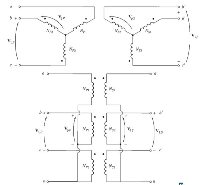
Three-phase transformer Connections
Y-Y connections:
Therefore, overall the voltage ratio on the transformer is VLSVLP=3VφS3VφP=a
The Y-Y connection has two very serious problems:
- If loads on the transformer circuit are unbalanced, then the voltages on the phases of the transformer can become severely unbalanced.
- Third-harmonic voltages can be large.
Three-phase transformer Connections
Y-Y connections:
Both the unbalance problem and the third-harmonic problem can be solved using one of two techniques:
- Solidly ground the neutrals of the transformers, especially the primary winding's neutral. This connection permits the additive third-harmonic components to cause a current flow in the neutral instead of building up large voltages. The neutral also provides a return path for any current imbalances in the load.
- Add a third (tertiary) winding connected in Δ to the transformer bank. If a third Δ connected winding is added to the transformer. then the third-harmonic components of voltage in the Δ will add up, causing a circulating current flow within the winding. This suppresses the third-harmonic components of voltage in the same manner as grounding the transformer neutrals.
Three-phase transformer Connections
Y-Y connections:
The Y-Y connection is rarely used for large amounts of power, but is not found too objectionable for local power distribution, especially within local industrial plants, where a neutral is required on both primary and secondary circuits, and where the neutral is grounded. One of the above techniques must be used any time a Y - Y transformer is installed. In practice, very few Y- Y transformers are used, since the same jobs can be done by one of the other types of three-phase transformers.
Three-phase transformer Connections
Y- Δ connections:
In this connection, the primary line voltage is related to the primary phase voltage by VLP=3VφP, while the secondary line voltage is equal to the secondary phase voltage VLS=VφS
The voltage ratio of each phase is VφSVφP=a
Therefore, overall relationship between the line voltage on the primary side of the bank and the line voltage on the secondary side of the bank is VLSVLP=VφS3VφP=3a
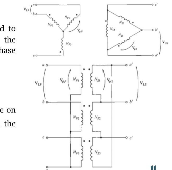
Three-phase transformer Connections
Y- Δ connections:
The Y- Δ connection has no problem with third-harmonic components in its voltages, since they are consumed in a circulating current on the a side. This connection is also more stable with respect to unbalanced loads, since they partially redistributes any imbalance that occurs.
This arrangement does have one problem, though. Because of the connection, the secondary voltage is shifted 30∘ relative to the primary voltage of the transformer. The fact that a phase shift has occurred can cause problems in paralleling the secondaries of two transformer banks together. The phase angles of transformer secondaries must be equal if they are to be paralleled, which means that attention must be paid to the direction of the 30∘ phase shift occurring in each transformer bank to be paralleled together.
Three-phase transformer Connections
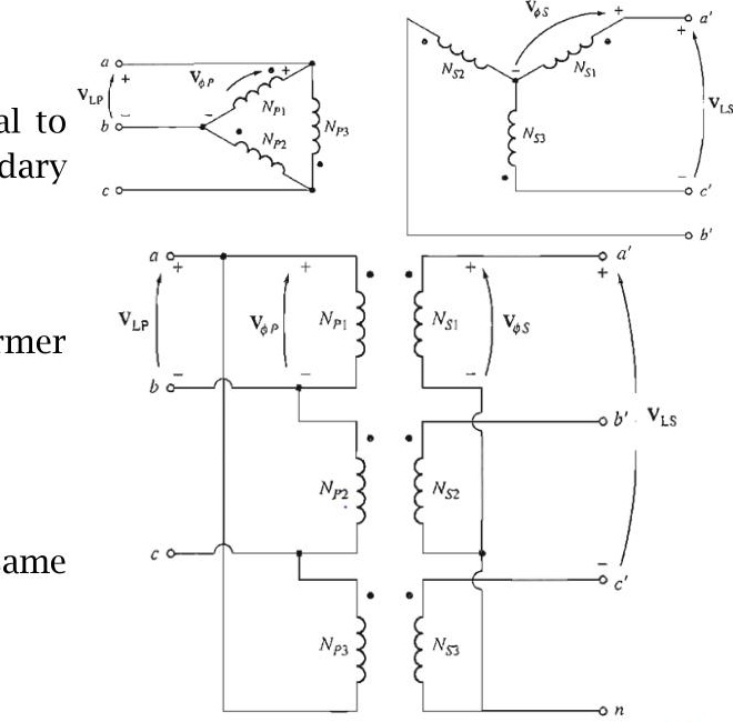
Δ -Y connections:
In a Δ -Y connection, the primary line voltage is equal to the primary-phase voltage VLP=VφP, while the secondary voltages are related by VLS=3VφS
Therefore, the line-to-line voltage ratio of this transformer connection is
VLSVLP=3VφSVφP=3a
This connection has the same advantages and the same phase shift as the Y- Δ transformer
Three-phase transformer Connections
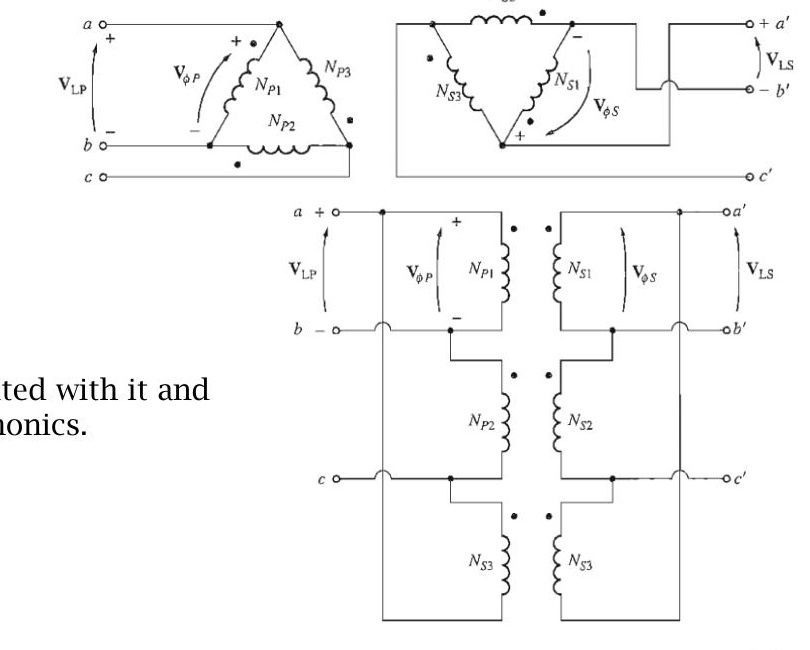
Δ - Δ connections:
In a Δ - Δ connection, VLP=VφP and VLS=VφS, so the relationship between primary and secondary line voltages is
VLSVLP=VφSVφP=a
This transformer has no phase shift associated with it and no problems with unbalanced loads or harmonics.
Three-phase transformation using two transformer
In addition to the standard three-phase transformer connections, there are ways to perform three-phase transformation with only two transformers. All techniques that create three phase power with only two transformers involve a reduction in the power-handling capability of the transformers, but they may be justified by certain economic situations. Some of the more important two-transformer connections are:
- The open- Δ (or V-V) connection
- The open-Y- open- Δ connection
- The Scott-T connection
- The three-phase T connection
The open- Δ (or V-V) connection
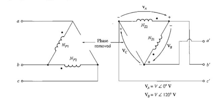
In some situations a full transformer bank may not be used to accomplish three phase transformation. For example, suppose that a Δ- Δ transformer bank composed of separate transformers has a damaged phase that must be removed for repair as shown in figure. If the two remaining secondary voltages are VA=V∠0∘ V and VB=V∠−120∘ V, then the voltage across the gap where the third transformer used to be is given by VC=−VA−VB
=−V∠0∘−V∠−120∘ =−V−(0.5 V−j0.0866 V) =−0.5 V+j0.0866 V =V∠120∘ V
The open- Δ (or V-V) connection
It may seem obvious that removal of one transformer would permit the remaining two to carry two-thirds of the load. This, however is not the case. If the rated secondary voltage and current of the transformers are VL and IS, respectively, the line current to the load of a closed Δ is 3IS. Therefore,
Closed- Δ kVA=10003VL3IS=10003VLIS
When one transformer is removed, the line is in series with the transformer coil and the line current is limited to the rated current of the transformer. Therefore
Open- Δ kVA=10003VLIS
The open- Δ (or V-V) connection
The ratio of the open- Δ kVA to the closed- Δ kVA is
closed- Δ kVAopen- Δ kVA=3VLIS3VLIS=33=0.577
It is thus seen that if one transformer of a closed- Δ system is removed, the remaining two transformer continue to supply three phase power. The load that can be carried without exceeding the ratings of the transformer is 57.7% of the original load rather than the expected 66.7 % (i.e. 2/3)
Problems
Practice example 14.4, 14.5 of Rosenblatt and also the related tutorial problem.
The open-Y open- Δ connection
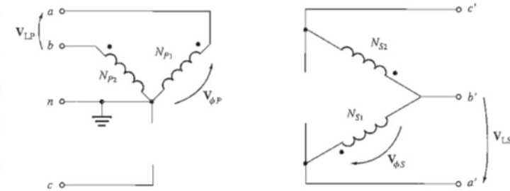
The open-wye-open-delta connection is very similar to the open delta connection except that the primary voltages are derived from two phases and the neutral. It is used to serve small commercial customers needing three-phase service in rural areas where all three phases are not yet present on the power poles. With this connection, a customer can get three phase service in a makeshift fashion until demand requires installation of the third phase on the power poles. A major disadvantage of this connection is that a very large return current must flow in the neutral of the primary circuit.
The Scott-T connection
The Scott-T connection is a way to derive two phases 90∘ apart from a three-phase power supply. In the early history of ac power transmission, two phase and three phase power systems were quite common. In those days, it was routinely necessary to interconnect two- and three-phase power systems, and the Scott-T transformer connection was developed for that purpose.
Today, two-phase power is primarily limited to certain control applications, but the Scott T is still used to produce the power needed to operate them.
The Scott-T connection
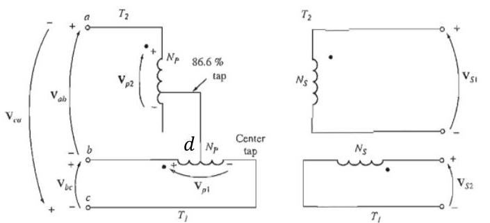
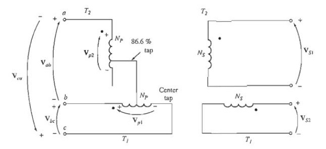
The Scott T consists of two single-phase transformers with identical ratings. One has a tap on its primary winding at 86.6 percent of full-load Voltage. They are connected as shown in Figure. The 86.6 percent tap of transformer T2, is connected to the center tap of transformer T1.
The Scott-T connection
Vad=Vab+Vbd
=VL∠−120∘+21VL∠0∘
=VL(−0.5−j0.866)+0.5VL
=−j0.866VL
=0.866VL∠90∘
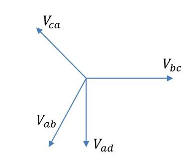
The voltage impressed across the T2 is 86.6 % of that across the main and lags it by 90∘ and result in a two phase output.
Three phase T connection
The Scott-T connection uses two transformers to convert three-phase power to two-phase power at a different voltage level. By a simple modification of that connection, the same two transformers can also convert three-phase power to three-phase power at a different voltage level.
Here both the primary and the secondary windings of transformer T, are tapped at the 86.6 percent point, and the taps are connected to the center taps of the corresponding windings on transformer T1. In this connection T1 is called the main transformer and T2 is called the teaser transformer. One major advantage of the three-phase T connection over the other three phase two transformer connections (the open-delta and open-wye-open-delta) is that a neutral can be connected to both the primary side and the secondary side of the transformer bank.
Vector group of transformer
The vector group indicates the phase difference between the primary and secondary sides, introduced due to that particular configuration of transformer windings connection. The transformer vector group is indicated on the Name Plate of transformer by the manufacturer.
The Determination of vector group of transformers is very important before connecting two or more transformers in parallel. If two transformers of different vector groups are connected in parallel then phase difference exist between the secondary of the transformers and large circulating current flows between the two transformers which is very detrimental.
Vector group of transformer
Note: The vector for the HV winding is taken as the reference vector and set at 12 o’clock. Displacement of the vectors of other windings from the reference vector, with anticlockwise rotation, is represented by the use of clock hour figure.
The hour indicator is used as the indicating phase displacement angle. Because there are 12 hours on a clock, and a circle consists out of 360∘, each hour represents 30∘. Thus 1=30∘, 2=60∘, 3=90∘, 6=180∘ and 12=0∘ or 360∘.
Vector group of transformer
Common Symbol Designation
Y or y – star winding
D or d – delta winding
N or n – neutral
0 to 12 – phase displacement in terms of clock position in multiples of 30∘
According to the standard, the notation should follow HV-LV-Phase displacement sequence with the HV winding in uppercase and LV winding in lowercase.
Vector group of transformer
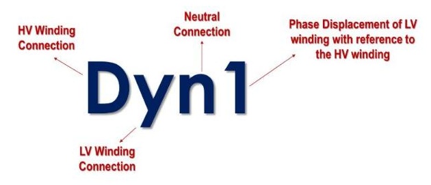
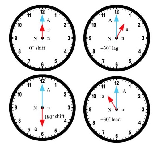
for example a winding configuration is shown in figure. As shown, the HV winding is connected in delta while the LV winding is connected in wye. This configuration belongs to the vector group of transformer Dyn1 where the LV lags the HV by 30∘.
Vector group of transformer
Example:
- Digit 0=0∘ that the LV phasor is in phase with the HV phasor
Digit 1=30∘ lagging (LV lags HV with 30∘) because rotation is anti-clockwise. - Digit 11=330∘ lagging or 30∘ leading (LV leads HV with 30∘)
- Digit 5=150∘ lagging (LV lags HV with 150∘)
- Digit 6=180∘ lagging (LV lags HV with 180∘)
Dyn11
Transformer has a delta connected primary winding (D) (HV) a star connected secondary (y) (LV) with the star point brought out (n) and a phase shift of 30 deg leading (11) (LV leading HV by 30 degree)