SlidesByMaam/L-10_ECE-2107.md
8.5 KB · commit d2f3b6e
Electrical Machines-I
ECE-2107
Transforer-SL3
Fariya Tabassum
Assistant Professor, Dept. of Electrical & Computer Engineering
Rajshahi University of Engineering & Technology, Rajshahi-6204
"And [remember] when your Lord proclaimed, If you are grateful, I will surely increase you [in favour] ".
[Sura Ibraheem]
Leakage Reactance:
The flux which leaks out of the core and does not link both windings is known as leakage flux. The flux which does pass completely through the core and links both windings is known as the mutual flux.
The voltages caused by the two leakage fluxes react as if they were induced in separate coils which are in series with each of the transformer windings. Because of this, the leakage fluxes may be replaced by pure reactances and known as the leakage reactances.
Effect of leakage flux
All of the flux in a real transformer is not common to both primary and secondary windings. The flux in a real transformer has three components: mutual flux, primary leakage flux and secondary leakage flux.
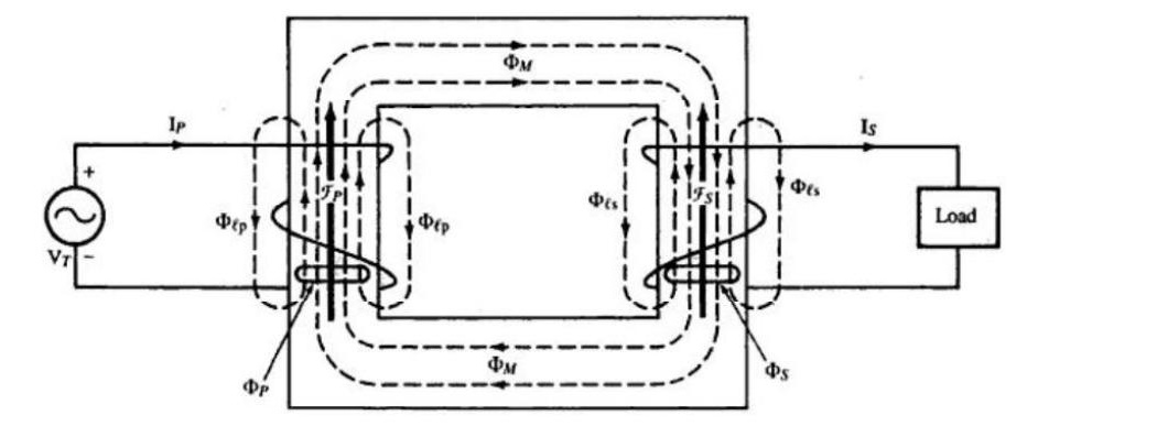
Effect of leakage flux
The primary leakage flux (caused by primary current) links only the primary turns. The secondary leakage flux (caused by secondary current) links only the secondary turns and the mutual flux (due to the magnetizing component of the exciting current) links both windings.
The relationship between coil flux, leakage flux and mutual flux for the respective primary and secondary coils are:
φP=φM+φlp φS=φM−φls
where:
φP= net flux in window of primary coil
φS= net flux in window of secondary coil
φM= mutual flux
φlp= leakage flux associated with the primary coil
φls= leakage flux associated with the secondary coil
Effect of leakage flux
φP=φM+φlp φS=φM−φls
The above equations illustrate how the leakage flux in both windings serves to reduce the output voltage of the secondary; the mutual flux is less than the available primary flux because of primary leakage and the net flux in the secondary is the mutual flux less the secondary leakage. Less flux in the secondary coil results in a lower secondary voltage than if no leakage were present.
Effect of leakage flux
The voltage drop caused by leakage flux is proportional to the load current. The greater the load current, the greater the magnitudes of both the primary and secondary ampere turns and hence the greater the respective leakage fluxes in both primary and secondary windings. Although leakage flux has an adverse effect on the transformer output voltage it proves an asset under severe short-circuit conditions, the large voltage drop caused by the intense leakage flux limits the current to a lower value than would otherwise occur if no leakage were present and thus helps to avoid damage to the transformer.
Transformation Ratio
The r.m.s value of thr induced emf in the entire primary winding, E1=4.44fN1φM \tag{1}
Similarly,
The r.m.s value of thr induced emf in the entire primary winding, E2=4.44fN2φM \tag{2}
From equations (2) and (1), we can write
E1E2=N1N2=K
This constant K is known as voltage transformation ratio.
If N2>N1 i. e. K>1 then transformer is step-up
N2<N1 i. e. K<1 then transformer is step-down
For ideal transformer, V1=E1 and E2=V2 i.e. the VA=output VA
V1I1=V2I2 or I1I2=V2V1=K1
Hence, currents are in the inverse ratio of the transformation ratio.
Equivalent Circuit
-
Equivalent Resistance
The equivalent secondary resistance as referred to primary is R2′=K2R2
The equivalent primary resistance as referred to secondary is R1′=K2R1
Equivalent or effective resistance of the transformer as referred to primary
R01=R1+R2′=R1+K2R2
Equivalent or effective resistance of the transformer as referred to secondary
R02=R2+R1′=R2+K2R1
Equivalent Circuit
-
Equivalent leakage reactances
The equivalent secondary reactance as referred to primary is X2′=K2X2
The equivalent secondary reactance as referred to secondary is X1′=K2X1
Equivalent or effective reactance of the transformer as referred to primary
X01=X1+X2′=X1+K2X2
Equivalent or effective reactance of the transformer as referred to secondary
X02=X2+X1′=X2+K2X1
Equivalent Circuit
The primary equivalent of the secondary induced voltage is E2′=KE2=E1
The primary equivalent of the secondary terminal or output voltage is V2′=KV2
primary equivalent of the secondary current is I2′=KI2
Equivalent Circuit
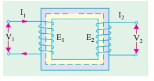
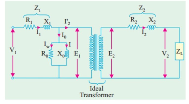
Equivalent Circuit
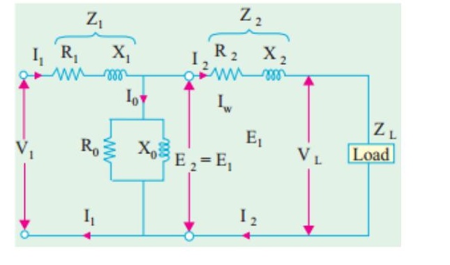
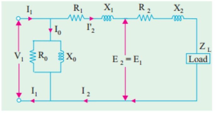
Phasor/ vector diagram with resistance and leakage reactance
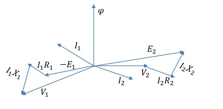
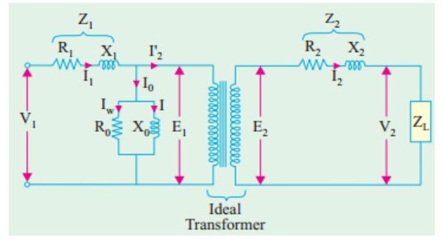
Phasor/ vector diagram with resistance and leakage reactance
When the load is resistive and capacitive
Transformer Regulation
As a real transformer has series impedances within it, the output voltage of a transformer varies with the load even if the input voltage remains constant. To conveniently compare transformers in this respect, it is customary to define a ( quantity called voltage regulation (VR). Full-load voltage regulation is a quantity that compares the output voltage of the transformer at no load with the output voltage at full load . It is defined by the equation
VR=VS,flVS,nl−VS,fl×100%
Transformer Tests
Open circuit or No load test:
- High voltage side is left open
- Cu loss is negligible
- Wattmeter gives the core loss
- Ammeter gives the no load primary current, I0
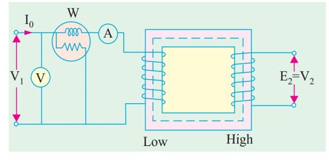
W=V1I0cosφ0;cosφ0=W/V1I0 Iμ=I0sinφ0;Iw=I0cosφ0 X0=V1/Iμ;R0=V1/Iw
Transformer Tests
Short circuit test:
- Low voltage side is short-circuited
- Core loss is negligible
- Wattmeter gives the combined primary and secondary Cu losses
- Equivalent impedance, leakage reactance and total resistance can be determined.
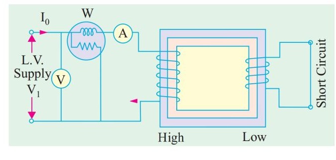
W=I12R01;cosφ0=W/V1I0
X01=(Z012−R012)
Problems
Practice example 14.7, 14.8, 14.9, 14.10 of Rosenblatt and 32.27, 32.35, 32.36, 32.40 of B. L. Theraza and also the related tutorial problem.