SlidesByMaam/L-09_ECE-2107.md
4.5 KB · commit d2f3b6e
Electrical Machines-I
ECE-2107
Transforer-SL2
Fariya Tabassum
Assistant Professor, Dept. of Electrical & Computer Engineering
Rajshahi University of Engineering & Technology, Rajshahi-6204
[Quranic Inscription]
“Guide us to the straight path—”.
[Sura Fatihah]
Transformer Construction
Go through the article 32.2, 32.3, 32.4 of the book written by B. L. Theraza to have a look at the transformer construction.
Transformer Phasor Diagram
Two cases are consider
- When transformer is on no load
- When it is loaded
When an actual transformer is put on load, there is iron loss in the core and copper loss in the windings (both primary and secondary) and these losses are not entirely negligible. Even when the transformer is on no-load, the primary input current is not wholly reactive.
Transformer Phasor Diagram
No load condition
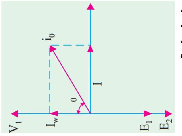
I0=Energizing current/ primary input current
Iw=Iron loss current
Iμ=magnetizing current
θ0=No load power factor angle
Transformer Phasor Diagram
No load condition
No-load input power W0=V1I0cosθ0
Iron loss current Iw=I0cosθ0
magnetizing current Iμ=I0sinθ0
For preparing your answer you can go through the article 14.5 of the book written by “Rosenblatt”
Transformer Phasor Diagram
No load condition
The followings should be noted:
- The no-load primary current I0 is very small as compared to the full-load primary current. It is about 1 % of the full-load current.
- As the permeability of the core varies with the instantaneous value of the exciting current, the wave of the exciting or magnetizing current is not truly sinusoidal and should not be represented by a vector.
Transformer Phasor Diagram
No load condition
- As I0 is very small, the no-load primary Cu loss is negligibly small which means that no-load primary input is practically equal to the iron loss in the transformer.
- As it is principally the core-loss which is responsible for shift in the current vector, angle θ0 is known as hysteresis angle of advance.
Problems
Practice example 14.4 of Rosenblatt and 32.9 of B. L. Theraza and also the related tutorial problem.
Transformer Phasor Diagram
Loaded condition
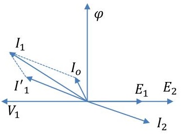
- When load is applied to the secondary terminals, in accordance with the Lenz’s law, the current that flows through the windings must act in such a direction as to oppose the flux set up by the primary current.
- When the flux is momentarily reduced, the induced emf in the primary winding is also reduced and as a result more current flows in the primary winding.
- The increased primary current will cause the flux to increase to its original value. When more load current flows in the secondary, the process is repeated and the primary current will again increase.
Transformer Phasor Diagram
Loaded condition
- The load current I2 is shown lagging the secondary induced voltage E2. I1′ is the current that flows in the primary winding to balance the demagnetizing effect of I2.
- Since flux φ remains constant, I0 must be the same current that energizes the transformer at no-load.
- I1, the actual current that flows in the primary, is therefore the phasor sum of currents I1′ and I0
Transformer Phasor Diagram
Loaded condition
When the load is purely resistive
For preparing your answer you can go through the article 32.10 of the book written by “B. L. Theraza”
Problems
Practice example 32.12, 32.13 and 32.14 of B. L. Theraza and also the related tutorial problem.