SlidesByMaam/L-08_ECE-2107.md
6.3 KB · commit d2f3b6e
Electrical Machines-I
ECE-2107
Transforer-SL1
Fariya Tabassum
Assistant Professor, Dept. of Electrical & Computer Engineering
Rajshahi University of Engineering & Technology, Rajshahi-6204
[Quranic Inscription]
“Never have I been in my supplication to You, my lord, unhappy”.
[Sura Maryam]
Transformer
Study Materials
- Direct and Alternating Current Machinery
Rosenblatt, Friedman
Transformer
Transformer is a device for transferring electrical energy from one circuit to another without a change in frequency.
Transformer
Uses
- They are used to raise or lower voltage in AC transmission and distribution systems
- Are used to provide reduced voltage at the starting of AC motors
- Are used to isolate one electric circuit from another
- Are used to superimpose an alternating voltage on a DC circuit
- Are used to provide low voltage for solid state control
- Are used for impedance matching purpose in communication network
Power Transformer
High Voltage Side:
The coils are wound with a greater number of turns of smaller cross-section conductor
Low Voltage Side:
The coils are wound with a small number of turns of large cross-section conductor
Core:
The core material is made of nonaging, cold-rolled, high-permeability silicon steel laminations; each lamination is insulated with a varnish or oxide coating to reduce eddy currents. The coils are wound with insulated aluminum conductor or insulated copper conductor, depending on design considerations.
Cooling:
Cooling is provided by air convection, forced air, insulating liquids or gas.
Power Transformer
There are two basic types of transformer used for power and distribution application
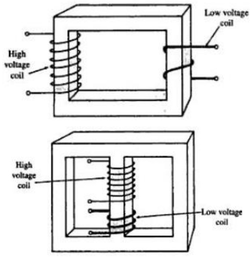
Core type: The primary and secondary coils wound on different legs. The wider spacing between primary and secondary in this type transformer gives advantages in high-voltage applications.
Shell type: Both the primary and secondary coils wound on the same leg. It has the advantage of less leakage flux
Efficiency of Transformer
The transformer accomplishes the change in voltage without the use of moving parts and therein lies its great advantage. The cost per kilowatt is comparatively low and the efficiency is high. As a matter of fact, the transformer is the most efficient piece of electrical machinery and efficiencies of 98 and 99 percent are no at all uncommon. Another important consideration is that, since there are no moving parts, maintenance is simpler and cheaper and the required insulation for the extremely high voltages obtained can more easily be constructed.
Principle of Transformer Action
Transformer with transient DC input:
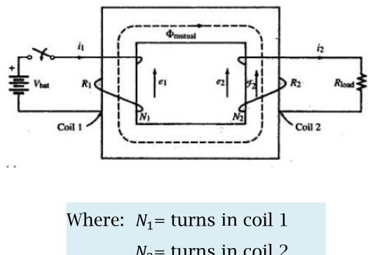
Where:
N1=turns in coil 1
N2=turns in coil 2
The coil 1 is connected to a battery through a switch and coil 2 is connected to a resistor. Closing the switch causes a clockwise buildup of flux in the iron core, generating a voltage in each coil that is proportional to
- the number of turns in the coil
- The rate of change of flux through the respective coils.
Assuming no leakage, the same flux (mutual flux) exists in both coils. Thus,
e1=N1dtdφ
e2=N2dtdφ
Principle of Transformer Action
Transformer with transient input:
Direction finding:
In accordance with Lenz’s law, the voltage generated in each coil will be induced in a direction that opposes the action that caused it.
The induced emf in coil 1 must be opposite in direction to the battery voltage. This opposing voltage, shown as e1 is called counter-emf (cemf)
For coil 2, the induced emf and associated current must be in a direction that will develop a counterclockwise mmf to oppose the buildup of flux in its window. Thus, with the direction of mmf known, the direction of induced emf and associated current may be determined by applying the right-hand rule to coil 2.
Principle of Transformer Action
Transformer with transient input:
Important Note:
“The induced emfs and secondary current in the figure are transients. When φmutual reaches steady state, dtdφ=0, the induced emfs=0 and i2=0”
Principle of Transformer Action
Watch the attached video termed as
“Transformers working & 3 phase transformer”
Principle of Transformer Action
Transformer with sinusoidal input:
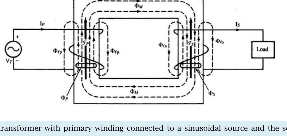
Figure shows a transformer with primary winding connected to a sinusoidal source and the secondary winding connected to a load. The currents and voltages are expressed as phasors. The direction of the induced voltages are determined as the same manner.
Principle of Transformer Action
Transformer with sinusoidal input:
The following assumptions are made:
- The permeability of the core is constant over the range of transformer operation and thus reluctance of the core is constant
- There is no leakage flux, hence the same flux links both primary and secondary windings.
The voltage induced in the primary and secondary windings by the sinusoidal variation of flux in the respective coil, expressed in terms of rms values, are
Ep=4.44Npfφmax
Es=4.44Nsfφmax
Dividing the above two equations
EsEp=NsNp
Where:
Ep=voltage induced in primary (V)
Es=voltage induced in secondary (V)
Np=turns in primary coil
Ns=turns in secondary coil
For preparing answer please go through Book written by “HUBERT” chapter 1, section 1.12