SlidesByMaam/L-02_ECE-2207.md
9.4 KB · commit d2f3b6e
Electrical Machines-I
ECE-2207
Induction Motor-SL1
Fariya Tabassum
Assistant Professor, Dept. of Electrical & Computer Engineering
Rajshahi University of Engineering & Technology, Rajshahi-6204
“My lord, increase me in knowledge”.
[Sura Ta Ha]
Important Terms Used in Electrical Machines
- Electrical machines (generator and motor) have two main parts, i. e., its stator and rotor. Stator is the stationary or non-moving part and rotor is the rotating or moving part. Stator is the outer part while rotor is the inner part.
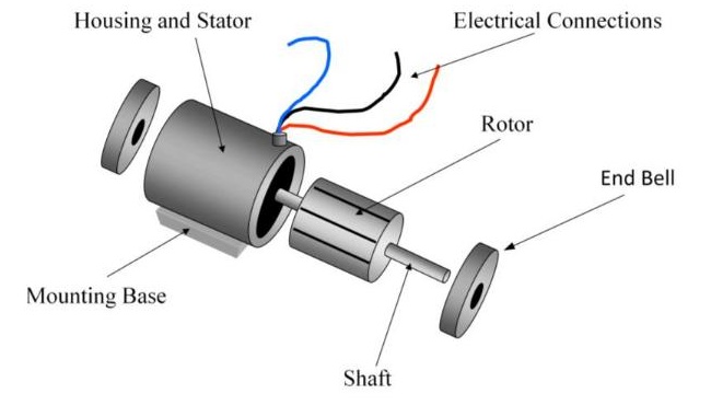
- The part of the machine from where the output is taken is called “Armature”. It can be either stationary (stator) or rotating (rotor).
AC Motor
- Synchronous Motor
- Asynchronous Motor
- Induction Motor
- Squirrel cage Induction Motor
- Slip-ring Induction Motor
- Commutator Motor
- Induction Motor
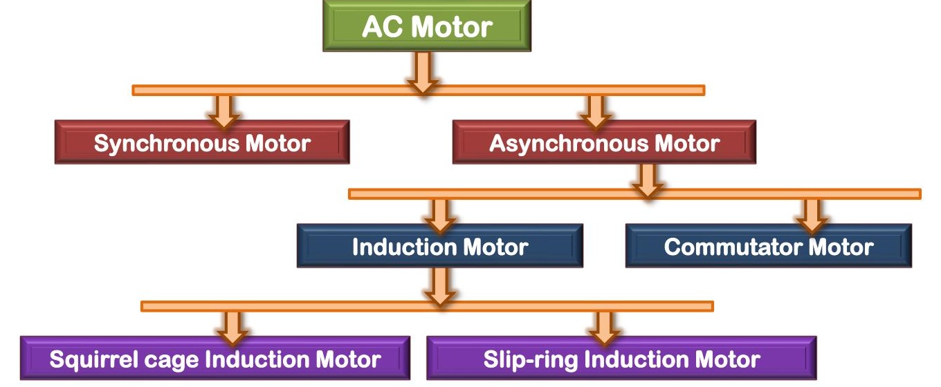
Mostly the Induction Motor is Known as Asynchronous Motor
DC Motor
Electric power is conducted directly to the armature (rotor) through brushes and commutator.
Induction Motor:
The rotor does not receive electric power by conduction but by induction in exactly the same way as the secondary of a 2-winding transformer receives its power from the primary. It requires no electrical connections to the rotating member, the transfer of energy from the stationary member to the rotating member is by means of electromagnetic induction. A rotating magnetic field, produced by stator, induces an alternating emf and current in the rotor. The resultant interaction of the induced rotor current with the rotating field of the stator winding produces motor torque. That is why such motors are known as induction motor. In fact, an induction motor can be treated as a rotating transformer, i. e., one in which primary winding is stationary but the secondary is free to rotate.
Induction Motor
Watch the attached video termed as “V-01” to be familiar with the parts of an induction motor
For further information about the parts you can go through the articles 34.3, 34.4 and 34.5 of the book written by “B. L. Theraza”
Induction Motor
Advantages:
- It has very simple and extremely rugged, almost unbreakable construction (especially squirrel cage type).
- Its cost is low and it is very reliable.
- It has sufficiently high efficiency. In normal running condition no brushes are needed, hence frictional losses are reduced. It has a reasonably good power factor.
- It requires minimum of maintenance.
- It starts up from rest and needs no extra starting motor and has not to be synchronized. Its starting arrangement is simple especially for squirrel cage type motor.
Disadvantages:
- Its speed cannot be varied without sacrificing some of its efficiency.
- Just like a dc shunt motor, its sped decreases with increase in load.
- Its starting torque is somewhat inferior to that of a dc shunt motor.
Induction Motor
Flux revolving theory
Rotating Magnetic Field
- First condition for the rotation of induction motor is to generate a rotating magnetic field at the stator.
- Single-phase ac supply alone cannot produce a rotating magnetic field. At least two-phase supply is needed.
Production of rotating magnetic field by 2-ϕ supply
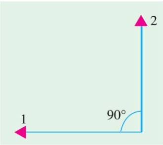
Let the fluxes produced by 2-ϕ supply are:
φ1=φmsinθ φ2=φmsin(θ−90∘)
The assumed positive direction of fluxes is shown in the figure.
Interval of 0∘,45∘,90∘,135∘ and 180∘ is considered
Rotating Magnetic Field
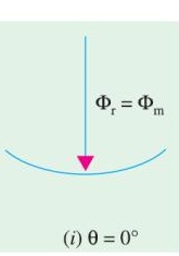
i. When θ=0∘
φ1=φmsin0∘=0 φ2=φmsin(0∘−90∘)=−φm
Resultant flux, φr=φm and is in negative direction
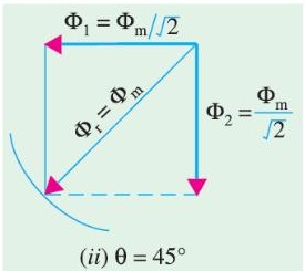
ii. When θ=45∘
φ1=φmsin45∘=2φm φ2=φmsin(45∘−90∘)=2−φm
Resultant flux, φr=(φm/2)2+(φm/2)2=φm
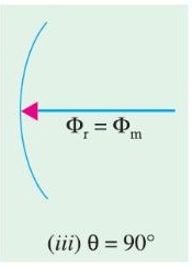
iii. When θ=90∘
φ1=φmsin90∘=φm φ2=φmsin(90∘−90∘)=0
Resultant flux, φr=φm and is in positive direction
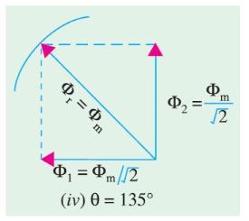
iv. When θ=135∘
φ1=φmsin135∘=2φm φ2=φmsin(135∘−90∘)=2φm
Resultant flux, φr=(φm/2)2+(φm/2)2=φm
Rotating Magnetic Field
v. When θ=180∘
φ1=φmsin180∘=0 φ2=φmsin(180∘−90∘)=φm
Resultant flux, φr=φm and is in positive direction
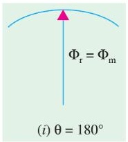
Note the direction of the resultant flux for the previous mentioned conditions. It is rotating
Important Conclusion
- The magnitude of the resultant flux is constant and is equal to φm that is the maximum flux due to either phase.
- The resultant flux rotates at synchronous speed. [i.e. the interval among 2 conditions is considered as 45∘ and the resultant flux also rotates by 45∘]
For preparing your answer you can go through the article 34.6 of the book written by “B. L. Theraza”
Rotating Magnetic Field
Production of rotating magnetic field by 3-ϕ supply
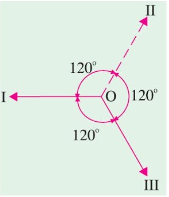
Let the fluxes produced by 3-ϕ supply are:
φ1=φmsinθ φ2=φmsin(θ−120∘) φ3=φmsin(θ+120∘)
The assumed positive direction of fluxes is shown in the figure.
Interval of 0∘,60∘,120∘ and 180∘ is considered
Rotating Magnetic Field
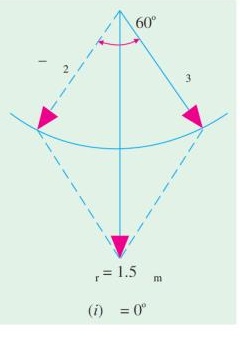
i. When θ=0∘
φ1=φmsin0∘=0 φ2=φmsin(0∘−120∘)=2−3φm φ3=φmsin(θ+120∘)=23φm
Resultant flux, φr=2×23φmcos260∘=23φm
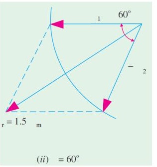
ii. When θ=60∘
φ1=φmsin60∘=23φm φ2=φmsin(0∘−120∘)=2−3φm φ3=φmsin(θ+120∘)=0
Resultant flux, φr=2×23φmcos260∘=23φm
Rotating Magnetic Field
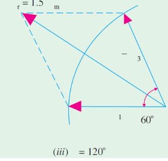
iii. When θ=120∘
φ1=φmsin120∘=23φm φ2=φmsin(0∘−120∘)=0 φ3=φmsin(θ+120∘)=2−3φm
Resultant flux, φr=23φm
Important Conclusion
- The magnitude of the resultant flux is of constant value and is equal to 23φm=1.5 times the maximum flux due to either phase.
- The resultant flux rotates at synchronous speed. [i.e. the interval among 2 conditions is considered as 60∘ and the resultant flux also rotates by 60∘]
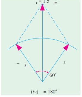
iv. When θ=180∘
φ1=φmsin60∘=0 φ2=φmsin(0∘−120∘)=23φm φ3=φmsin(θ+120∘)=2−3φm
Resultant flux, φr=23φm
For preparing your answer you can go through the article 34.7 of the book written by “B. L. Theraza” or article 8.3 of the book written by “V. K. Mehta”