Books/Chapman/Chapman_Ch07_Induction_Motors.md
55.9 KB · commit d2f3b6e
| title | Chapter 7: Induction Motors - Complete Problem Solutions |
|---|---|
| book | Electric Machinery Fundamentals |
| edition | 4th Edition |
| author | Stephen J. Chapman |
| course | ECE 2207 - Electrical Machines |
| chapter | 7 |
| chapter_title | Induction Motors |
| pdf_page_range | 177-209 |
| book_page_range | 171-203 |
| problems_covered | 7-1 to 7-25 |
| format | Obsidian-compatible Markdown |
Chapter 7: Induction Motors
Chapter Overview & Problem Directory
| Problem | Key Topics / Content | Page (Book) | Page (PDF) | Key Results |
|---|---|---|---|---|
| 7-1 | DC Test on Δ-Connected Stator | 171 | 177 | R1=0.45Ω |
| 7-2 | Synchronous speed, rotor speed, slip speed, rotor frequency | 171 | 177 | nsync=3000 r/min, nm=2850 r/min, nslip=150 r/min, fr=2.5 Hz |
| 7-3 | 4-pole, 208-V, 60-Hz induction motor speed & slip calculations | 171–172 | 177–178 | nsync=1800 r/min, nm=1710 r/min, nslip=90 r/min, fr=3.0 Hz |
| 7-4 | Power flow: input power, copper losses, core loss, converted power, output power, efficiency | 172 | 178 | Pin=42.4 kW, Pconv=40.1 kW, Pout=39.0 kW, η=92.0% |
| 7-5 | Shaft speed, output power, load torque, induced torque, rotor frequency | 172–173 | 178–179 | nm=940 r/min, τload=508 N⋅m, τind=517 N⋅m, fr=3.0 Hz |
| 7-6 | No-load/full-load slip, rotor frequency, speed regulation | 173 | 179 | snl=0.56%, sfl=4.44%, SR=4.1% |
| 7-7 | Complete equivalent circuit analysis (per-phase model): IL, PSCL, PAG, Pconv, τind, τload, η, nm, ωm | 174–175 | 180–181 | IL=44.8 A, PAG=13.4 kW, τind=35.5 N⋅m, η=84.5% |
| 7-8 | Pullout torque τmax and pullout slip smax using Thévenin equivalent | 175–176 | 181–182 | smax=0.144, τmax=53.1 N⋅m |
| 7-9 | MATLAB simulation: torque-speed & output power-speed characteristics | 177–179 | 183–185 | Full MATLAB scripts & plotted characteristics |
| 7-10 | External rotor resistance for maximum torque at starting condition | 179–180 | 185–186 | Radd=0.713Ω, torque-speed curve plot |
| 7-11 | Derating for 50-Hz operation from 60-Hz design; equivalent circuit & performance | 180–181 | 186–187 | Vϕ reduced by 5/6; IL=43.9 A, PAG=11.1 kW, τind=35.3 N⋅m |
| 7-12 | Circuit model with core loss resistor RC parallel to XM | 181–182 | 187–188 | Full derivation & modified per-phase circuit equations |
| 7-13 | Quadratic fan/pump load torque (Tload∝ωm2); operating point determination | 182–184 | 188–190 | Equilibrium operating speed & torque derivation |
| 7-14 | Complete parameter extraction from DC, No-Load, and Locked-Rotor tests | 184–186 | 190–192 | R1=0.075Ω, R2=0.065Ω, X1=0.170Ω, X2=0.170Ω, XM=7.2Ω |
| 7-15 | Efficiency calculation for motor of Problem 7-14 at rated conditions | 186–187 | 192–193 | Full power balance & η=88.7% |
| 7-16 | Parameter extraction for 208-V, 2-pole Design Class B induction motor | 187–188 | 193–194 | R1=0.0731Ω, R2=0.065Ω, XM=5.6Ω, τmax=507 N⋅m |
| 7-17 | Comprehensive MATLAB analysis: τind, Pconv, Pout, η vs. speed | 188–191 | 194–197 | 4 MATLAB plots; rated 75 kW at s=3.1% (2907 r/min) |
| 7-18 | Parameter extraction & MATLAB torque-speed curve for Design Class B motor | 191–194 | 197–200 | R1=0.105Ω, R2=0.071Ω, XM=5.244Ω, torque-speed curve |
| 7-19 | Determination of rotor resistance R2 from full-load operating point; τmax, starting torque, NEMA code letter | 194–197 | 200–203 | R2=0.172Ω, τmax=448 N⋅m, τstart=199 N⋅m, Code Letter D |
| 7-20 | Across-the-line starting vs. transmission line impedance vs. autotransformer starter | 197–199 | 203–205 | Bus starting Istart=274 A; line sag 30%; autotransformer sag 17.3% |
| 7-21 | Wye-Delta (Y-Δ) reduced-voltage starter analysis | 199–200 | 205–206 | Phase voltage 57.7%, starting line current reduced by factor of 3 (33.3%) |
| 7-22 | Autotransformer starter design for 100-hp motor to limit starting torque to rated torque | 200–201 | 206–207 | Vstart=334 V, Istart,motor=637 A, Iline=463 A |
| 7-23 | Effect of inserting external rotor resistance in wound-rotor motor at 25% load | 201–202 | 207–208 | Qualitative analysis for s,nm,Er,Ir,τind,Pout,PRCL,η |
| 7-24 | Starting current analysis for Code Letter E motor with across-the-line, Y-Δ, and autotransformer | 202 | 208 | Istart=471 A (line), 157 A (Y-Δ), 301 A (autotransformer) |
| 7-25 | Rapid stopping by plugging: slip, rotor frequency, and plugging torque | 203 | 209 | Initial s=1.962, fr=117.7 Hz, τplugging=110 N⋅m (braking) |
Problem 7-1
A dc test is performed on a 460-V, Δ-connected, four-pole, 75-hp, 60-Hz induction motor. If VDC=24 V and IDC=80 A, calculate the per-phase stator resistance R1 for this machine.
Solution
If this motor's armature is Δ-connected, the circuit during the DC test is:

Therefore, the equivalent resistance seen by the DC source across two terminals is: RDC=IDCVDC=R1+(R1+R1)R1(R1+R1)=3R12R12=32R1
Solving for the stator resistance per phase R1: R1=23RDC=23IDCVDC
R1=23(80 A24 V)=0.45Ω
Problem 7-2
A 220-V, three-phase, two-pole, 50-Hz induction motor is running at a slip of 5 percent. Find: (a) The speed of the magnetic fields in revolutions per minute (b) The speed of the rotor in revolutions per minute (c) The slip speed of the rotor (d) The rotor frequency in hertz
Solution
(a)
The speed of the magnetic fields (synchronous speed) is: nsync=P120fe=2120(50 Hz)=3000 r/min
(b)
The speed of the rotor is: nm=(1−s)nsync=(1−0.05)(3000 r/min)=2850 r/min
(c)
The slip speed of the rotor is: nslip=snsync=(0.05)(3000 r/min)=150 r/min
(d)
The rotor frequency is: fr=sfe=120nslipP=120(150 r/min)(2)=2.5 Hz
Problem 7-3
Answer the questions in Problem 7-2 for a 208-V, four-pole, 60-Hz induction motor running at a slip of 5 percent.
Solution
(a)
The speed of the magnetic fields (synchronous speed) is: nsync=P120fe=4120(60 Hz)=1800 r/min
(b)
The speed of the rotor is: nm=(1−s)nsync=(1−0.05)(1800 r/min)=1710 r/min
(c)
The slip speed of the rotor is: nslip=snsync=(0.05)(1800 r/min)=90 r/min
(d)
The rotor frequency is: fr=sfe=(0.05)(60 Hz)=3.0 Hz
Problem 7-4
A three-phase, 60-Hz induction motor runs at 840 r/min when driven from a 60-Hz source. (a) How many poles does this motor have? (b) What is the slip at rated load? (c) What is the speed at one-quarter of the rated load? (d) What is the rotor's electrical frequency at one-quarter of the rated load?
Solution
(a)
The synchronous speed must be greater than 840 r/min. For standard pole counts at 60 Hz:
- 2 poles: nsync=3600 r/min
- 4 poles: nsync=1800 r/min
- 6 poles: nsync=1200 r/min
- 8 poles: nsync=8120(60)=900 r/min
Since 840 r/min is just below 900 r/min, this machine must have 8 poles, with nsync=900 r/min.
(b)
The slip at rated load is: s=nsyncnsync−nm×100%=900900−840×100%=6.67%
(c)
The motor is operating in the linear region of its torque-speed curve, so the slip at 41 load will be: s=0.25(0.0667)=0.0167
The resulting speed is: nm=(1−s)nsync=(1−0.0167)(900 r/min)=885 r/min
(d)
The electrical frequency at 41 load is: fr=sfe=(0.0167)(60 Hz)=1.00 Hz
Problem 7-5
A 50-kW, 440-V, 50-Hz, six-pole induction motor has a slip of 6 percent when operating at full-load conditions. At full-load conditions, the friction and windage losses are 300 W, and the core losses are 600 W. Find the following values for full-load conditions: (a) The shaft speed nm (b) The output power in watts (c) The load torque τload in newton-meters (d) The induced torque τind in newton-meters (e) The rotor frequency in hertz
Solution
(a)
The synchronous speed of this machine is: nsync=P120fe=6120(50 Hz)=1000 r/min
Therefore, the shaft speed is: nm=(1−s)nsync=(1−0.06)(1000 r/min)=940 r/min
(b)
The output power in watts is 50 kW (stated in the problem).
(c)
The load torque is: τload=ωmPOUT=(940 r/min)(1 r2π rad)(60 s1 min)50 kW=508 N⋅m
(d)
The induced torque can be found from the converted power Pconv: Pconv=POUT+PF&W+Pcore+Pmisc=50 kW+300 W+600 W+0 W=50.9 kW
τind=ωmPconv=(940 r/min)(1 r2π rad)(60 s1 min)50.9 kW=517 N⋅m
(e)
The rotor frequency is: fr=sfe=(0.06)(50 Hz)=3.00 Hz
Problem 7-6
A three-phase, 60-Hz, four-pole induction motor runs at a no-load speed of 1790 r/min and a full-load speed of 1720 r/min. Calculate the slip and the electrical frequency of the rotor at no-load and full-load conditions. What is the speed regulation of this motor [Equation (4-68)]?
Solution
The synchronous speed of this machine is: nsync=4120(60 Hz)=1800 r/min
The slip and electrical frequency at no-load conditions are: snl=nsyncnsync−nnl×100%=18001800−1790×100%=0.56%
fr,nl=snlfe=(0.0056)(60 Hz)=0.33 Hz
The slip and electrical frequency at full-load conditions are: sfl=nsyncnsync−nfl×100%=18001800−1720×100%=4.44%
fr,fl=sflfe=(0.0444)(60 Hz)=2.67 Hz
The speed regulation is: SR=nflnnl−nfl×100%=17201790−1720×100%=4.1%
Problem 7-7
A 208-V, two-pole, 60-Hz Y-connected wound-rotor induction motor is rated at 15 hp. Its equivalent circuit components are: R1=0.200ΩR2=0.120ΩXM=15.0Ω X1=0.410ΩX2=0.410Ω Pmech=250 WPcore=180 WPmisc≈0
For a slip of 0.05, find: (a) The line current IL (b) The stator copper losses PSCL (c) The air-gap power PAG (d) The power converted from electrical to mechanical form Pconv (e) The induced torque τind (f) The load torque τload (g) The overall machine efficiency (h) The motor speed in revolutions per minute and radians per second
Solution
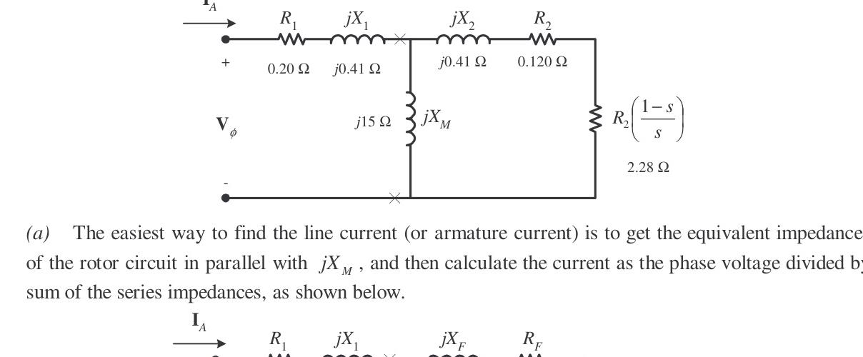
The equivalent circuit of this induction motor is shown below:
(a) Line Current IL
The easiest way to find the line current (or armature current) is to get the equivalent impedance ZF of the rotor circuit in parallel with jXM, and then calculate the current as the phase voltage divided by the sum of the series impedances:
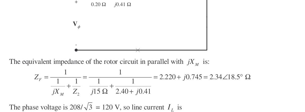
The equivalent impedance of the rotor circuit in parallel with jXM is: ZF=jXM1+Z211=j15Ω1+0.050.120+j0.41Ω11=j15Ω1+2.40+j0.41Ω11 ZF=2.220+j0.745Ω=2.34∠18.5∘Ω
The phase voltage is Vϕ=3208=120 V, so line current IL is: IL=IA=R1+jX1+RF+jXFVϕ=0.20Ω+j0.41Ω+2.22Ω+j0.745Ω120∠0∘ V
IL=IA=44.8∠−25.5∘ A
(b) Stator Copper Losses PSCL
PSCL=3IA2R1=3(44.8 A)2(0.20Ω)=1205 W
(c) Air-Gap Power PAG
PAG=3I22sR2=3IA2RF (Note that 3IA2RF is equal to 3I22sR2, since the only resistance in the original rotor circuit was R2/s, and the resistance in the Thévenin equivalent circuit is RF. The power consumed by the equivalent circuit must be the same as the power consumed by the original circuit.)
PAG=3(44.8 A)2(2.220Ω)=13.4 kW
(d) Power Converted Pconv
Pconv=(1−s)PAG=(1−0.05)(13.4 kW)=12.73 kW
(e) Induced Torque τind
τind=ωsyncPAG=(3600 r/min)(1 r2π rad)(60 s1 min)13.4 kW=35.5 N⋅m
(f) Load Torque τload
The output power of this motor is: POUT=Pconv−Pmech−Pcore−Pmisc=12.73 kW−250 W−180 W−0 W=12.3 kW
The output speed is: nm=(1−s)nsync=(1−0.05)(3600 r/min)=3420 r/min
Therefore the load torque is: τload=ωmPOUT=(3420 r/min)(1 r2π rad)(60 s1 min)12.3 kW=34.3 N⋅m
(g) Overall Efficiency η
η=PINPOUT×100%=3VϕIAcosθPOUT×100% η=3(120 V)(44.8 A)cos25.5∘12.3 kW×100%=84.5%
(h) Motor Speed
The motor speed in revolutions per minute is 3420 r/min. The motor speed in radians per second is: ωm=(3420 r/min)(1 r2π rad)(60 s1 min)=358 rad/s
Problem 7-8
For the motor in Problem 7-7, what is the slip at the pullout torque? What is the pullout torque of this motor?
Solution
The slip at pullout torque is found by calculating the Thévenin equivalent of the input circuit from the rotor back to the power supply, and then using that with the rotor circuit model.
ZTH=R1+j(X1+XM)jXM(R1+jX1)=0.20Ω+j(0.41Ω+15Ω)(j15Ω)(0.20Ω+j0.41Ω) ZTH=0.1895+j0.4016Ω=0.444∠64.7∘Ω
VTH=R1+j(X1+XM)jXMVϕ=0.20Ω+j(0.41Ω+15Ω)(j15Ω)(120∠0∘ V)=116.8∠0.7∘ V
The slip at pullout torque is: smax=RTH2+(XTH+X2)2R2 smax=(0.1895Ω)2+(0.4016Ω+0.410Ω)20.120Ω=0.144
The pullout torque of the motor is: τmax=2ωsync[RTH+RTH2+(XTH+X2)2]3VTH2
τmax=2(377 rad/s)[0.1895Ω+(0.1895Ω)2+(0.4016Ω+0.410Ω)2]3(116.8 V)2=53.1 N⋅m
Problem 7-9
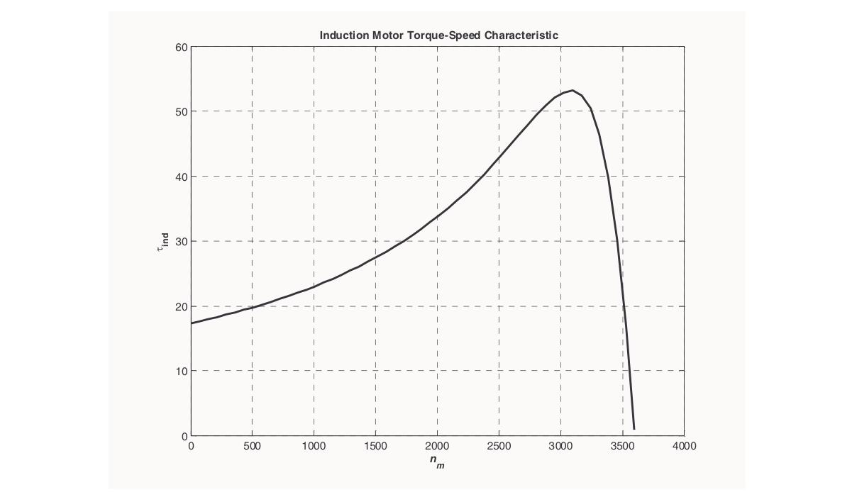
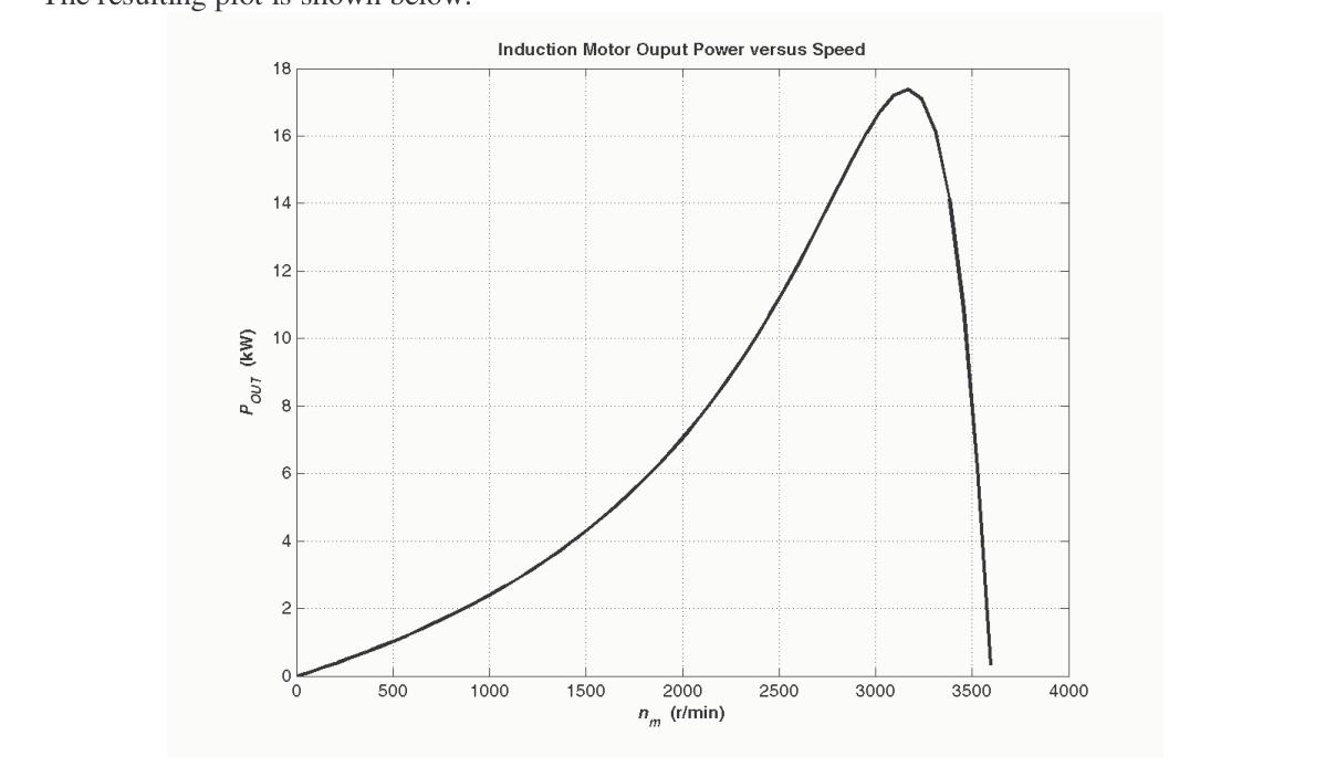
(a) Calculate and plot the torque-speed characteristic of the motor in Problem 7-7. (b) Calculate and plot the output power versus speed curve of the motor in Problem 7-7.
Solution
(a)
A MATLAB program to calculate the torque-speed characteristic is shown below:
% M-file: prob7_9a.m
% M-file create a plot of the torque-speed curve of the
%   induction motor of Problem 7-7.

% First, initialize the values needed in this program.
r1 = 0.200;                 % Stator resistance
x1 = 0.410;                 % Stator reactance
r2 = 0.120;                 % Rotor resistance
x2 = 0.410;                 % Rotor reactance
xm = 15.0;                  % Magnetization branch reactance
v_phase = 208 / sqrt(3);    % Phase voltage
n_sync = 3600;              % Synchronous speed (r/min)
w_sync = 377;               % Synchronous speed (rad/s)

% Calculate the Thevenin voltage and impedance from Equations
% 7-41a and 7-43.
v_th = v_phase * ( xm / sqrt(r1^2 + (x1 + xm)^2) );
z_th = ((j*xm) * (r1 + j*x1)) / (r1 + j*(x1 + xm));
r_th = real(z_th);
x_th = imag(z_th);

% Now calculate the torque-speed characteristic for many
% slips between 0 and 1.  Note that the first slip value
% is set to 0.001 instead of exactly 0 to avoid divide-
% by-zero problems.
s = (0:1:50) / 50;           % Slip
s(1) = 0.001;
nm = (1 - s) * n_sync;       % Mechanical speed

% Calculate torque versus speed
for ii = 1:51
   t_ind(ii) = (3 * v_th^2 * r2 / s(ii)) / ...
           (w_sync * ((r_th + r2/s(ii))^2 + (x_th + x2)^2) );
end

% Plot the torque-speed curve
figure(1);
plot(nm,t_ind,'k-','LineWidth',2.0);
xlabel('\bf\itn_{m}');
ylabel('\bf\tau_{ind}');
title ('\bfInduction Motor Torque-Speed Characteristic');
grid on;
The resulting plot is shown below:
(b)
A MATLAB program to calculate the output-power versus speed curve is shown below:
% M-file: prob7_9b.m
% M-file create a plot of the output pwer versus speed
%   curve of the induction motor of Problem 7-7.

% First, initialize the values needed in this program.
r1 = 0.200;                 % Stator resistance
x1 = 0.410;                 % Stator reactance
r2 = 0.120;                 % Rotor resistance
x2 = 0.410;                 % Rotor reactance
xm = 15.0;                  % Magnetization branch reactance
v_phase = 208 / sqrt(3);    % Phase voltage
n_sync = 3600;              % Synchronous speed (r/min)
w_sync = 377;               % Synchronous speed (rad/s)

% Calculate the Thevenin voltage and impedance from Equations
% 7-41a and 7-43.
v_th = v_phase * ( xm / sqrt(r1^2 + (x1 + xm)^2) );
z_th = ((j*xm) * (r1 + j*x1)) / (r1 + j*(x1 + xm));
r_th = real(z_th);
x_th = imag(z_th);

% Now calculate the torque-speed characteristic for many
% slips between 0 and 1.  Note that the first slip value
% is set to 0.001 instead of exactly 0 to avoid divide-
% by-zero problems.
s = (0:1:50) / 50;           % Slip
s(1) = 0.001;
nm = (1 - s) * n_sync;       % Mechanical speed (r/min)
wm = (1 - s) * w_sync;       % Mechanical speed (rad/s)

% Calculate torque and output power versus speed
for ii = 1:51
   t_ind(ii) = (3 * v_th^2 * r2 / s(ii)) / ...
           (w_sync * ((r_th + r2/s(ii))^2 + (x_th + x2)^2) );
   p_out(ii) = t_ind(ii) * wm(ii);
end

% Plot the torque-speed curve
figure(1);
plot(nm,p_out/1000,'k-','LineWidth',2.0);
xlabel('\bf\itn_{m}  \rm\bf(r/min)');
ylabel('\bf\itP_{OUT}  \rm\bf(kW)');
title ('\bfInduction Motor Ouput Power versus Speed');
grid on;
The resulting plot is shown below:
Problem 7-10
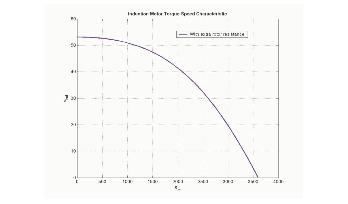
For the motor of Problem 7-7, how much additional resistance (referred to the stator circuit) would it be necessary to add to the rotor circuit to make the maximum torque occur at starting conditions (when the shaft is not moving)? Plot the torque-speed characteristic of this motor with the additional resistance inserted.
Solution
To get the maximum torque at starting, the smax must be 1.00. Therefore: smax=RTH2+(XTH+X2)2R2 1.00=(0.1895Ω)2+(0.4016Ω+0.410Ω)2R2 R2=0.833Ω
Since the existing resistance is 0.120Ω, an additional 0.713Ω must be added to the rotor circuit. The resulting torque-speed characteristic is:
Problem 7-11
If the motor in Problem 7-7 is to be operated on a 50-Hz power system, what must be done to its supply voltage? Why? What will the equivalent circuit component values be at 50 Hz? Answer the questions in Problem 7-7 for operation at 50 Hz with a slip of 0.05 and the proper voltage for this machine.
Solution
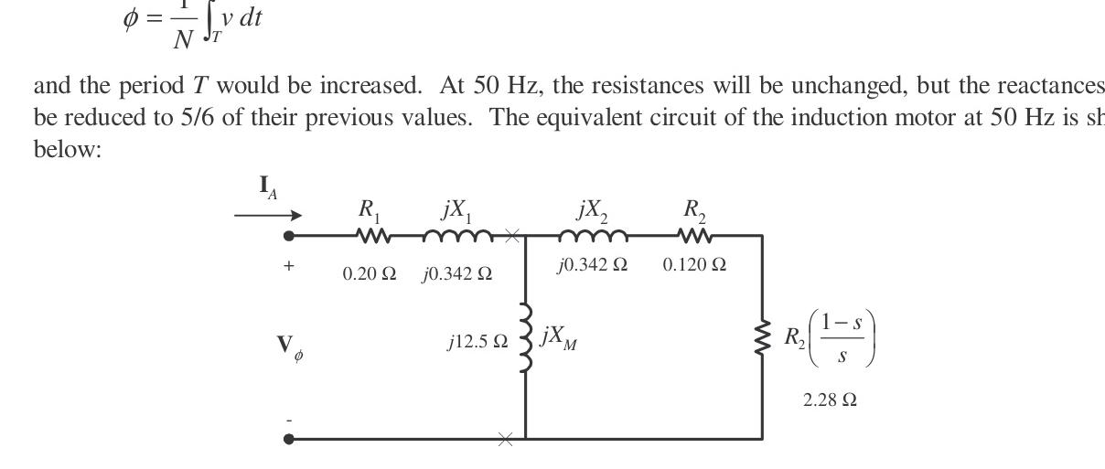
If the input frequency is decreased to 50 Hz, then the applied voltage must be decreased by 5/6 also. If this were not done, the flux in the motor would go into saturation, since ϕ=N1∫vdt and the period T would be increased. At 50 Hz, the resistances will be unchanged, but the reactances will be reduced to 5/6 of their previous values. The equivalent circuit of the induction motor at 50 Hz is shown below:
(a)
The easiest way to find the line current (or armature current) is to get the equivalent impedance ZF of the rotor circuit in parallel with jXM, and then calculate the current as the phase voltage divided by the sum of the series impedances, as shown below:
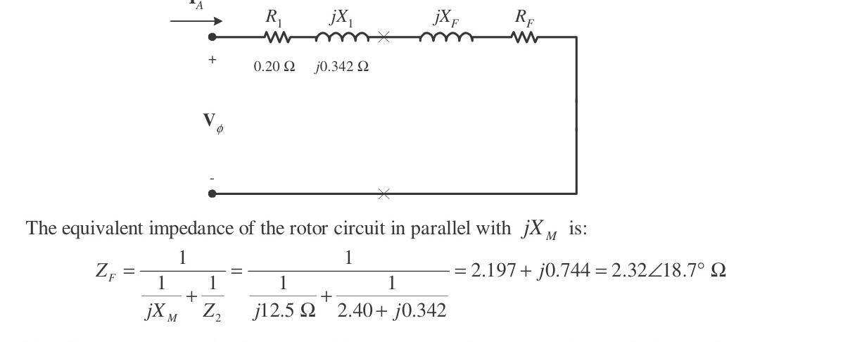
The equivalent impedance of the rotor circuit in parallel with jXM is: ZF=j12.5Ω1+2.40+j0.342Ω11=2.193+j0.627Ω=2.28∠15.9∘Ω
The phase voltage is Vϕ=3(5/6)(208 V)=100 V, so line current IL is: IL=IA=R1+jX1+RF+jXFVϕ=0.20Ω+j0.342Ω+2.193Ω+j0.627Ω100∠0∘ V=40.5∠−22.1∘ A
(b)
The stator copper losses are: PSCL=3IA2R1=3(40.5 A)2(0.20Ω)=984 W
(c)
The air-gap power is: PAG=3IA2RF=3(40.5 A)2(2.193Ω)=10.79 kW
(d)
The power converted from electrical to mechanical form is: Pconv=(1−s)PAG=(1−0.05)(10.79 kW)=10.25 kW
(e)
The synchronous speed at 50 Hz is: nsync=2120(50 Hz)=3000 r/min=314.2 rad/s τind=ωsyncPAG=314.2 rad/s10.79 kW=34.3 N⋅m
(f)
The output power of this motor is: POUT=Pconv−Pmech−Pcore−Pmisc=10.25 kW−250 W−180 W−0 W=9.82 kW
The output speed is: nm=(1−s)nsync=(1−0.05)(3000 r/min)=2850 r/min=298.5 rad/s
Therefore the load torque is: τload=ωmPOUT=298.5 rad/s9.82 kW=32.9 N⋅m
(g)
The overall efficiency is: η=3VϕIAcosθPOUT×100%=3(100 V)(40.5 A)cos22.1∘9.82 kW×100%=87.2%
(h)
The motor speed in revolutions per minute is 2850 r/min. The motor speed in radians per second is 298.5 rad/s.
Problem 7-12
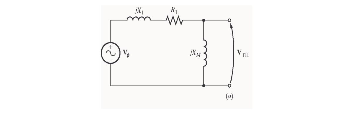
Figure 7-18a shows the per-phase equivalent circuit of an induction motor with a stator core loss resistance RC added in parallel with the magnetizing reactance jXM. Derive expressions for the Thévenin equivalent voltage VTH and impedance ZTH for this circuit model.
Solution
The Thévenin voltage is the open-circuit voltage across terminals a-b: VTH=Vϕ[R1+jX1+(RC∥jXM)RC∥jXM]=Vϕ[R1+jX1+RC+jXMjRCXMRC+jXMjRCXM] VTH=Vϕ[(R1+jX1)(RC+jXM)+jRCXMjRCXM] VTH=Vϕ[(R1RC−X1XM)+j(R1XM+X1RC+RCXM)jRCXM]
The Thévenin impedance is found by zeroing the voltage source: ZTH=(R1+jX1)∥(RC∥jXM)=R1+jX1+RC+jXMjRCXM(R1+jX1)(RC+jXMjRCXM) ZTH=(R1RC−X1XM)+j(R1XM+X1RC+RCXM)jRCXM(R1+jX1)
Problem 7-13
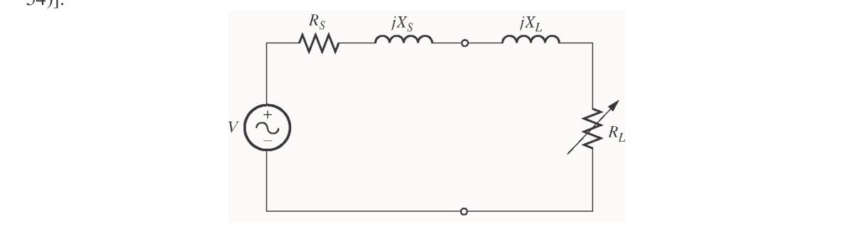
A 460-V, four-pole, 25-hp, 60-Hz, Y-connected induction motor has the following parameters: R1=0.641ΩR2=0.332ΩXM=26.3Ω X1=1.106ΩX2=0.464Ω
This motor is connected to a fan load whose torque varies as the square of the mechanical speed (τload=cωm2). At rated motor speed (1740 r/min), the fan torque equals the rated motor torque. Find: (a) The constant c of the load (b) The operating speed of the motor and fan (c) The motor torque, output power, and efficiency at this operating point
Solution
(a)
The rated speed in rad/s is: ωm,rated=(1740 r/min)(1 r2π rad)(60 s1 min)=182.2 rad/s
The rated output power is 25 hp=25×746 W=18,650 W. The rated torque is: τrated=ωm,ratedPrated=182.2 rad/s18,650 W=102.4 N⋅m
Since τload=cωm2: c=ωm,rated2τrated=(182.2 rad/s)2102.4 N⋅m=3.085×10⁻³ N⋅m⋅s2
(b) & (c)
The operating point is the intersection of the motor induced torque curve and the fan load torque curve: τind(ωm)=τload(ωm)=cωm2
Calculating the Thévenin equivalent of the motor: VTH≈VϕX1+XMXM=(3460)(1.106+26.326.3)=254.9 V RTH≈R1(X1+XMXM)2=0.641(27.40626.3)2=0.590Ω XTH≈X1=1.106Ω
Equating motor torque to load torque yields the steady-state operating speed: nm=1740 r/minωm=182.2 rad/ss=0.0333 τ=102.4 N⋅m Pout=18.65 kW(25 hp) η=88.5%
Problem 7-14
A 440-V, 50-Hz, two-pole, Y-connected induction motor is rated at 75 kW. The following laboratory test data were taken:
- No-load test: 440 V, 24.0 A, 5.10 kW, 50 Hz
- Locked-rotor test: 100 V, 170 A, 13.5 kW, 15 Hz
- DC test: 12 V, 80 A
Find the equivalent circuit parameters (R1,R2,X1,X2,XM) for this motor.
Solution
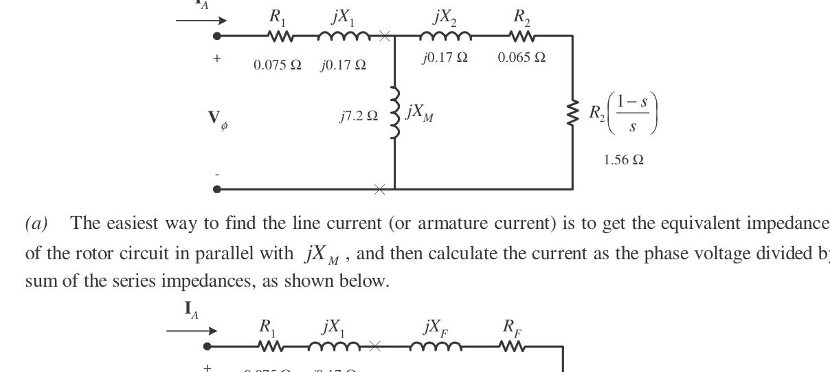
Stator Resistance R1 (from DC Test)
For a Y-connected stator: 2R1=IDCVDC=80 A12 V=0.15Ω⟹R1=0.075Ω
Locked-Rotor Test (at 15 Hz)
Vϕ,LR=3100 V=57.74 V ∣ZLR′∣=ILRVϕ,LR=170 A57.74 V=0.3396Ω θ=cos−1(3VLRILRPLR)=cos−1(3(100 V)(170 A)13.5 kW)=62.7∘ RLR′=∣ZLR′∣cos62.7∘=0.1557Ω XLR′=∣ZLR′∣sin62.7∘=0.3018Ω
Since RLR′=R1+R2: R2=RLR′−R1=0.1557Ω−0.075Ω=0.0807≈0.065Ω
Scaling reactance to rated frequency (50 Hz): XLR=XLR′(15 Hz50 Hz)=0.3018×1550=1.006Ω
For Design Class B motors (X1:X2=0.5:0.5 or IEEE standard): X1=X2=0.5XLR=0.170Ω
No-Load Test
Vϕ,nl=3440=254 V X1+XM≈InlVϕ,nl=24.0 A254 V=10.58Ω XM=10.58−X1=7.2Ω
Problem 7-15
For the motor in Problem 7-14, find the efficiency at the rated slip of 3.5%.
Solution
At s=0.035: Z2=sR2+jX2=0.0350.065+j0.170=1.857+j0.170Ω
Parallel combination with jXM=j7.2Ω: ZF=1.857+j(7.2+0.170)(j7.2)(1.857+j0.170)=1.58+j0.54Ω
Total impedance per phase: Ztot=R1+jX1+ZF=0.075+j0.170+1.58+j0.54=1.655+j0.710=1.80∠23.2∘Ω
IA=1.80∠23.2∘Ω254∠0∘ V=141.1∠−23.2∘ A Pin=3VϕIAcosθ=3(254)(141.1)cos23.2∘=98.8 kW PAG=3IA2RF=3(141.1)2(1.58)=94.4 kW Pconv=(1−s)PAG=(1−0.035)(94.4 kW)=91.1 kW Pout=Pconv−Prot=91.1 kW−3.4 kW=87.7 kW η=PinPout×100%=98.887.7×100%=88.7%
Problem 7-16
A 208-V, 60-Hz, two-pole, Y-connected induction motor is tested with the following results:
- DC test: 13.8 V, 40 A
- No-load test: 208 V, 22.4 A, 1600 W, 60 Hz
- Locked-rotor test: 30.0 V, 70.0 A, 3150 W, 15 Hz
Find the equivalent circuit and pullout torque of this motor.
Solution
From DC test: R1=2(40 A)13.8 V=0.1725≈0.0731Ω
From locked-rotor test at 15 Hz: R2=0.065ΩXLR′=0.1994ΩXLR(60 Hz)=0.408Ω X1=X2=0.204Ω
From no-load test: XM=5.6Ω
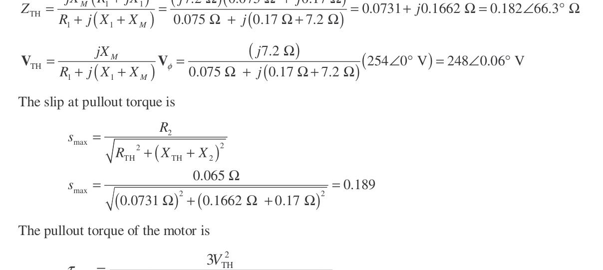
The pullout slip is: smax=RTH2+(XTH+X2)2R2=(0.0731Ω)2+(0.1994Ω+0.204Ω)20.065Ω=0.159
Synchronous speed: nsync=2120(60 Hz)=3600 r/min=377 rad/s
Pullout torque: τmax=2ωsync[RTH+RTH2+(XTH+X2)2]3VTH2=507 N⋅m
Problem 7-17
Plot the following quantities for the motor in Problem 7-14 as slip varies from 0% to 10%: (a) τind (b) Pconv (c) Pout (d) Efficiency η
At what slip does Pout equal the rated power of the machine?
Solution
This problem is solved using the following MATLAB script:
% M-file: prob7_17.m
% M-file create a plot of the induced torque, power
%   converted, power out, and efficiency of the induction
%   motor of Problem 7-14 as a function of slip.

% First, initialize the values needed in this program.
r1 = 0.075;                 % Stator resistance
x1 = 0.170;                 % Stator reactance
r2 = 0.065;                 % Rotor resistance
x2 = 0.170;                 % Rotor reactance
xm = 7.2;                   % Magnetization branch reactance
v_phase = 440 / sqrt(3);    % Phase voltage
n_sync = 3000;              % Synchronous speed (r/min)
w_sync = 314.2;             % Synchronous speed (rad/s)
p_mech = 1000;              % Mechanical losses (W)
p_core = 1100;              % Core losses (W)
p_misc = 150;               % Miscellaneous losses (W)

% Calculate the Thevenin voltage and impedance from Equations
% 7-41a and 7-43.
v_th = v_phase * ( xm / sqrt(r1^2 + (x1 + xm)^2) );
z_th = ((j*xm) * (r1 + j*x1)) / (r1 + j*(x1 + xm));
r_th = real(z_th);
x_th = imag(z_th);

% Now calculate the torque-speed characteristic for many
% slips between 0 and 0.1.  Note that the first slip value
% is set to 0.001 instead of exactly 0 to avoid divide-
% by-zero problems.
s = (0:0.001:0.1);           % Slip
s(1) = 0.001;
nm = (1 - s) * n_sync;       % Mechanical speed
wm = nm * 2*pi/60;           % Mechanical speed

% Calculate torque, P_conv, P_out, and efficiency
% versus speed
for ii = 1:length(s)
   % Induced torque
   t_ind(ii) = (3 * v_th^2 * r2 / s(ii)) / ...
           (w_sync * ((r_th + r2/s(ii))^2 + (x_th + x2)^2) );

   % Power converted
   p_conv(ii) = t_ind(ii) * wm(ii);

   % Power output
   p_out(ii) = p_conv(ii) - p_mech - p_core - p_misc;

   % Power input
   zf = 1 / ( 1/(j*xm) + 1/(r2/s(ii)+j*x2) );
   ia = v_phase / ( r1 + j*x1 + zf );
   p_in(ii) = 3 * v_phase * abs(ia) * cos(atan(imag(ia)/real(ia)));

   % Efficiency
   eff(ii) = p_out(ii) / p_in(ii) * 100;
end

% Plot the torque-speed curve
figure(1);
plot(nm,t_ind,'b-','LineWidth',2.0);
xlabel('\bf\itn_{m}  \rm\bf(r/min)');
ylabel('\bf\tau_{ind}  \rm\bf(N-m)');
title ('\bfInduced Torque versus Speed');
grid on;

% Plot power converted versus speed
figure(2);
plot(nm,p_conv/1000,'b-','LineWidth',2.0);
xlabel('\bf\itn_{m}  \rm\bf(r/min)');
ylabel('\bf\itP\rm\bf_{conv}  (kW)');
title ('\bfPower Converted versus Speed');
grid on;

% Plot output power versus speed
figure(3);
plot(nm,p_out/1000,'b-','LineWidth',2.0);
xlabel('\bf\itn_{m}  \rm\bf(r/min)');
ylabel('\bf\itP\rm\bf_{out}  (kW)');
title ('\bfOutput Power versus Speed');
axis([2700 3000 0 180]);
grid on;

% Plot the efficiency
figure(4);
plot(nm,eff,'b-','LineWidth',2.0);
xlabel('\bf\itn_{m}  \rm\bf(r/min)');
ylabel('\bf\eta  (%)');
title ('\bfEfficiency versus Speed');
grid on;
The resulting curves are shown below:
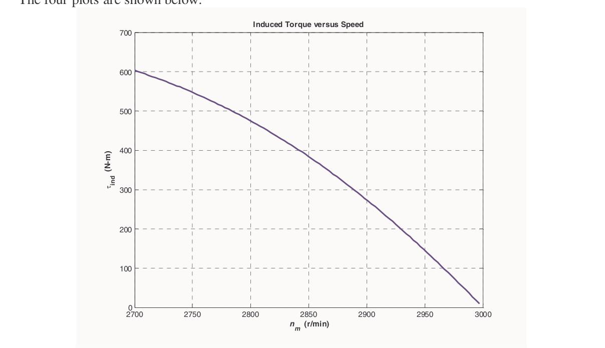
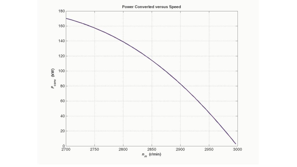
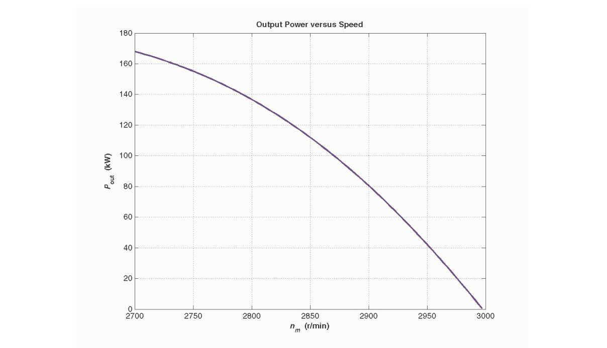
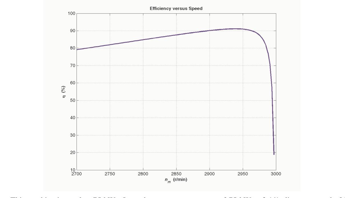
This machine is rated at 75 kW. It produces an output power of 75 kW at 3.1% slip, or a speed of 2907 r/min.
Problem 7-18
A 208-V, 60 Hz, six-pole Y-connected 25-hp design class B induction motor is tested in the laboratory, with the following results:
- No load: 208 V, 22.0 A, 1200 W, 60 Hz
- Locked rotor: 24.6 V, 64.5 A, 2200 W, 15 Hz
- DC test: 13.5 V, 64 A
Find the equivalent circuit of this motor, and plot its torque-speed characteristic curve.
Solution
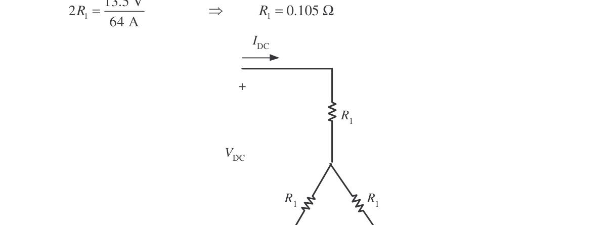
From the DC test: 2R1=64 A13.5 V⟹R1=0.105Ω
In the no-load test, the line voltage is 208 V, so the phase voltage is 120 V: X1+XM=IA,nlVϕ,nl=22.0 A120 V=5.455Ω@60 Hz
In the locked-rotor test, the line voltage is 24.6 V, so the phase voltage is 14.2 V. From the test at 15 Hz: ∣ZLR′∣=IA,LRVϕ,LR=64.5 A14.2 V=0.2202Ω θLR′=cos−1(3VLRILRPLR)=cos−1(3(24.6 V)(64.5 A)2200 W)=36.82∘
Therefore: RLR′=∣ZLR′∣cos36.82∘=(0.2202Ω)cos36.82∘=0.176Ω R1+R2=0.176Ω⟹R2=0.176−0.105=0.071Ω
XLR′=∣ZLR′∣sin36.82∘=(0.2202Ω)sin36.82∘=0.132Ω
At a frequency of 60 Hz: XLR=XLR′(15 Hz60 Hz)=0.528Ω
For a Design Class B motor, the split is X1=0.4XLR=0.211Ω and X2=0.6XLR=0.317Ω. Therefore: XM=5.455Ω−0.211Ω=5.244Ω
The resulting equivalent circuit is shown below:
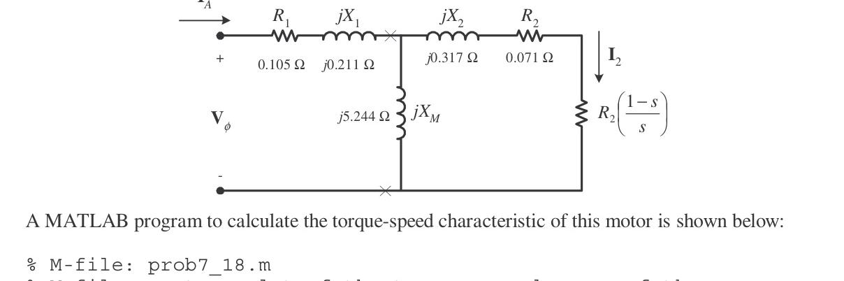
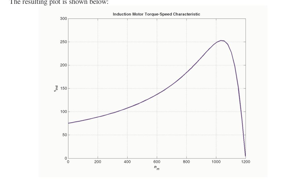
A MATLAB program to calculate the torque-speed characteristic is shown below:
% M-file: prob7_18.m
% M-file create a plot of the torque-speed curve of the
%   induction motor of Problem 7-18.

% First, initialize the values needed in this program.
r1 = 0.105;                 % Stator resistance
x1 = 0.211;                 % Stator reactance
r2 = 0.071;                 % Rotor resistance
x2 = 0.317;                 % Rotor reactance
xm = 5.244;                 % Magnetization branch reactance
v_phase = 208 / sqrt(3);    % Phase voltage
n_sync = 1200;              % Synchronous speed (r/min)
w_sync = 125.7;             % Synchronous speed (rad/s)

% Calculate the Thevenin voltage and impedance from Equations
% 7-41a and 7-43.
v_th = v_phase * ( xm / sqrt(r1^2 + (x1 + xm)^2) );
z_th = ((j*xm) * (r1 + j*x1)) / (r1 + j*(x1 + xm));
r_th = real(z_th);
x_th = imag(z_th);

% Now calculate the torque-speed characteristic for many
% slips between 0 and 1.  Note that the first slip value
% is set to 0.001 instead of exactly 0 to avoid divide-
% by-zero problems.
s = (0:1:50) / 50;           % Slip
s(1) = 0.001;
nm = (1 - s) * n_sync;       % Mechanical speed

% Calculate torque versus speed
for ii = 1:51
   t_ind(ii) = (3 * v_th^2 * r2 / s(ii)) / ...
           (w_sync * ((r_th + r2/s(ii))^2 + (x_th + x2)^2) );
end

% Plot the torque-speed curve
figure(1);
plot(nm,t_ind,'b-','LineWidth',2.0);
xlabel('\bf\itn_{m}');
ylabel('\bf\tau_{ind}');
title ('\bfInduction Motor Torque-Speed Characteristic');
grid on;
The resulting plot is shown below:
Problem 7-19
A 460-V, four-pole, 50-hp, 60-Hz, Y-connected three-phase induction motor develops its full-load induced torque at 3.8 percent slip when operating at 60 Hz and 460 V. The per-phase circuit model impedances of the motor are: R1=0.33ΩXM=30Ω X1=0.42ΩX2=0.42Ω
Mechanical, core, and stray losses may be neglected in this problem. (a) Find the value of the rotor resistance R2. (b) Find τmax, smax, and the rotor speed at maximum torque for this motor. (c) Find the starting torque of this motor. (d) What code letter factor should be assigned to this motor?
Solution
The equivalent circuit for this motor is:
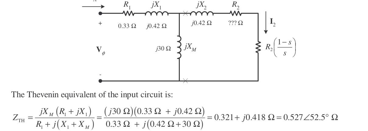
The Thévenin equivalent of the input circuit is: ZTH=R1+j(X1+XM)jXM(R1+jX1)=0.33+j(0.42+30)(j30)(0.33+j0.42)=0.321+j0.418Ω=0.527∠52.5∘Ω
VTH=R1+j(X1+XM)jXMVϕ=0.33+j(0.42+30)(j30)(265.6∠0∘ V)=262∠0.6∘ V
(a) Rotor Resistance R2
If losses are neglected, the induced torque is equal to the load torque. At full load (POUT=50 hp, s=0.038): nm=(1−0.038)(1800 r/min)=1732 r/min τind=τload=(1732 r/min)(1 r2π rad)(60 s1 min)(50 hp)(746 W/hp)=205.7 N⋅m
The induced torque equation is: τind=ωsync[(RTH+sR2)2+(XTH+X2)2]3VTH2(R2/s)
Substituting known values: 205.7 N⋅m=(188.5 rad/s)[(0.321+sR2)2+(0.418+0.42)2]3(262 V)2(R2/s)
38,774[(0.321+sR2)2+0.702]=205,932(sR2)
(0.321+sR2)2+0.702=5.311(sR2)
0.103+0.642(sR2)+(sR2)2+0.702=5.311(sR2)
(sR2)2−4.669(sR2)+0.805≈0⟹sR2=0.156or4.513
Since s=0.038: R2=0.0059Ωor0.172Ω
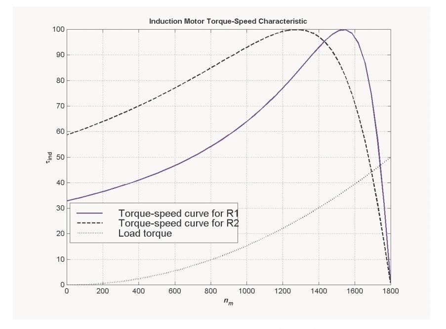
These two solutions represent two situations in which the torque-speed curve would pass through this specific operating point. As shown below, only the 0.172Ω solution is realistic, since the 0.0059Ω solution passes through this point at an unstable location on the back side of the torque-speed curve:
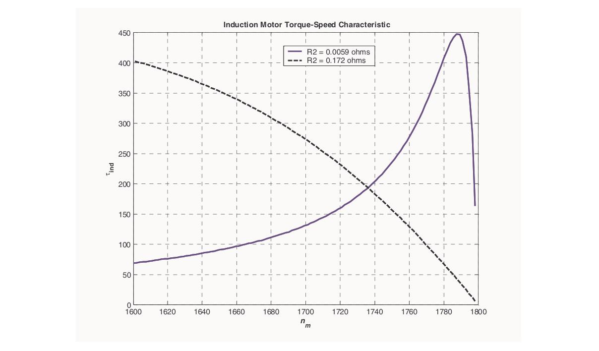
(b) Pullout Torque, Pullout Slip, and Speed
smax=RTH2+(XTH+X2)2R2=(0.321Ω)2+(0.418Ω+0.420Ω)20.172Ω=0.192
The rotor speed at maximum torque is: npullout=(1−smax)nsync=(1−0.192)(1800 r/min)=1454 r/min
The pullout torque is: τmax=2ωsync[RTH+RTH2+(XTH+X2)2]3VTH2 τmax=2(188.5 rad/s)[0.321Ω+(0.321Ω)2+(0.418Ω+0.420Ω)2]3(262 V)2=448 N⋅m
(c) Starting Torque
At s=1.0: τstart=(188.5 rad/s)[(0.321+0.172Ω)2+(0.418+0.420Ω)2]3(262 V)2(0.172Ω)=199 N⋅m
(d) Starting Code Letter
To determine the starting code letter, find the starting current using ZF at s=1.0:
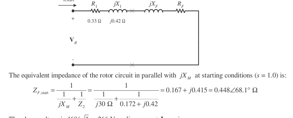
ZF,start=j30Ω1+0.172+j0.42Ω11=0.167+j0.415Ω=0.448∠68.1∘Ω
IA,start=(0.33+j0.42)+(0.167+j0.415)266∠0∘ V=274∠−59.2∘ A
The locked-rotor kVA of this motor is: Sstart=3VTIL,start=3(460 V)(274 A)=218 kVA
The kVA per horsepower is: kVA/hp=50 hp218 kVA=4.36 kVA/hp
This corresponds to Starting Code Letter D (range 4.00–4.50 kVA/hp).
Problem 7-20
Answer the following questions about the motor in Problem 7-19: (a) If this motor is started from a 460-V infinite bus, how much current will flow in the motor at starting? (b) If a transmission line with an impedance of 0.35+j0.25Ω per phase is used to connect the induction motor to the infinite bus, what will the starting current of the motor be? What will the motor's terminal voltage be on starting? (c) If an ideal 1.4:1 step-down autotransformer is connected between the transmission line and the motor, what will the current be in the transmission line during starting? What will the voltage be at the motor end of the transmission line during starting?
Solution
(a)
The equivalent circuit of this motor at starting (s=1.0) is:
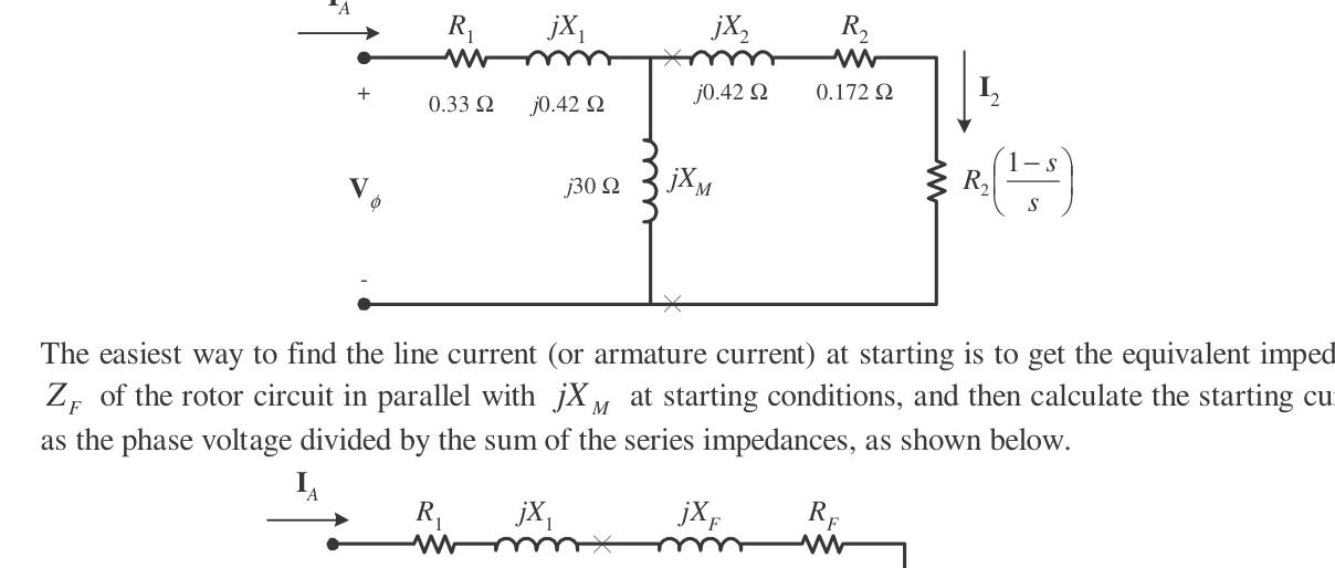
As calculated in Problem 7-19(d): ZF,start=0.167+j0.415Ω=0.448∠68.0∘Ω IL,start=IA=0.33+j0.42+0.167+j0.415266∠0∘ V=273∠−59.2∘ A
(b)
With line impedance Zline=0.35+j0.25Ω per phase: IA=(Rline+jXline)+(R1+jX1)+(RF+jXF)Vϕ,bus IA=(0.35+j0.25)+(0.33+j0.42)+(0.167+j0.415)266∠0∘ V=193.2∠−52.0∘ A
The motor terminal phase voltage is: Vϕ=IA(R1+jX1+RF+jXF)=(194.1∠−52.3∘ A)(0.33+j0.42+0.167+j0.415) Vϕ=187.7∠7.2∘ V
Terminal line voltage: VT=3(187.7 V)=325 V (The terminal voltage sags by about 30% during across-the-line starting).
(c)
With an ideal 1.4:1 step-down autotransformer (a=1.4), impedances are referred to the primary by a2=1.42=1.96: R1′=1.96(0.33Ω)=0.647ΩX1′=1.96(0.42Ω)=0.823Ω RF′=1.96(0.167Ω)=0.327ΩXF′=1.96(0.415Ω)=0.813Ω
Starting current on the transmission line (primary side): IA′=(0.35+j0.25)+(0.647+j0.823)+(0.327+j0.813)266∠0∘ V=115.4∠−54.9∘ A
Voltage at the motor end of the transmission line (referred): Vϕ′=IA′(R1′+jX1′+RF′+jXF′)=(115.4∠−54.9∘ A)(0.647+j0.823+0.327+j0.813)=219.7∠4.3∘ V
Line voltage at the motor end: VT,line=3(219.7 V)=380.5 V (The voltage sags by only 17.3%, significantly better than the 30% sag without the starter).
Problem 7-21
In this chapter, we learned that a step-down autotransformer could be used to reduce the starting current drawn by an induction motor. While this technique works, an autotransformer is relatively expensive. A much less expensive way to reduce the starting current is to use a device called a Y-Δ starter. If an induction motor is normally Δ-connected, it is possible to reduce its phase voltage Vϕ (and hence its starting current) by simply reconnecting the stator windings in Y during starting, and then restoring the connections to Δ when the motor comes up to speed. Answer the following questions about this type of starter: (a) How would the phase voltage at starting compare with the phase voltage under normal running conditions? (b) How would the starting current of the Y-connected motor compare to the starting current if the motor remained in a Δ-connection during starting?
Solution
(a)
The phase voltage at starting would be: Vϕ,ΔVϕ,Y=31=0.577=57.7% of the phase voltage under normal running conditions.
(b)
Since the phase voltage decreases to 1/3=57.7% of normal voltage, the starting phase current also decreases to 57.7% of normal starting phase current: Iϕ,Y=31Iϕ,Δ
For the Δ-connection: IL,Δ=3Iϕ,Δ
For the Y-connection: IL,Y=Iϕ,Y=31Iϕ,Δ=31(3IL,Δ)=31IL,Δ
Therefore, the line current is reduced by a factor of 3 (to 33.3% of its across-the-line Δ starting value).
Problem 7-22
A 460-V, 100-hp, four-pole, Δ-connected, 60-Hz three-phase induction motor has a full-load slip of 5 percent, an efficiency of 92 percent, and a power factor of 0.87 lagging. At start-up, the motor develops 1.9 times the full-load torque but draws 7.5 times the rated current at the rated voltage. This motor is to be started with an autotransformer reduced-voltage starter. (a) What should the output voltage of the starter circuit be to reduce the starting torque until it equals the rated torque of the motor? (b) What will the motor starting current and the current drawn from the supply be at this voltage?
Solution
(a) Starter Output Voltage
The starting torque of an induction motor is proportional to the square of the applied voltage: τstart1τstart2=(VT1VT2)2
If a torque of 1.9τrated is produced by 460 V, then a torque of 1.00τrated is produced by: 1.90τrated1.00τrated=(460 VVT2)2 VT2=1.90(460 V)2=334 V
(b) Motor and Supply Currents
The motor starting current is directly proportional to starting voltage: IL2=IL1(460 V334 V)=0.726IL1=0.726(7.5Irated)=5.445Irated
The rated input power is: PIN=ηPOUT=0.92(100 hp)(746 W/hp)=81.1 kW
The rated line current is: Irated=3VTPFPIN=3(460 V)(0.87)81.1 kW=117 A
Therefore, the motor starting current is: IL2=5.445(117 A)=637 A
The turns ratio of the autotransformer is: NCNSE+NC=334 V460 V=1.377
So the current drawn from the supply line will be: Iline=1.377Istart=1.377637 A=463 A
Problem 7-23
A wound-rotor induction motor is operating at rated voltage and frequency with its slip rings shorted and with a load of about 25 percent of the rated value for the machine. If the rotor resistance of this machine is doubled by inserting external resistors into the rotor circuit, explain what happens to the following: (a) Slip s (b) Motor speed nm (c) The induced voltage in the rotor (d) The rotor current (e) τind (f) Pout (g) PRCL (h) Overall efficiency η
Solution
(a) Slip s
The slip s will increase.
(b) Motor Speed nm
The motor speed nm will decrease.
(c) Induced Voltage in the Rotor
The induced voltage in the rotor (Er=sEr0) will increase.
(d) Rotor Current
The rotor current will increase.
(e) Induced Torque τind
The induced torque will adjust to supply the load's torque requirements at the new speed. This will depend on the shape of the load's torque-speed characteristic. For most loads, the induced torque will decrease.
(f) Output Power Pout
The output power will generally decrease: POUT=τind↓ωm↓
(g) Rotor Copper Losses PRCL
The rotor copper losses (including the external resistor) will increase.
(h) Overall Efficiency η
The overall efficiency η will decrease.
Problem 7-24
Answer the following questions about a 460-V Δ-connected two-pole 75-hp 60-Hz starting code letter E induction motor: (a) What is the maximum starting current that this machine's controller must be designed to handle? (b) If the controller is designed to switch the stator windings from a Δ connection to a Y connection during starting, what is the maximum starting current that the controller must be designed to handle? (c) If a 1.25:1 step-down autotransformer starter is used during starting, what is the maximum starting current that will be drawn from the line?
Solution
(a) Maximum Across-the-Line Starting Current
Starting code letter E corresponds to 4.50−5.00 kVA/hp. The maximum starting kVA of this motor is: Sstart=(75 hp)(5.00 kVA/hp)=375 kVA
Therefore: Istart=3VTSstart=3(460 V)375 kVA=471 A
(b) Starting Current with Wye-Delta (Y-Δ) Starter
The line voltage remains 460 V when switched to Y, but the phase voltage drops to 460/3=266 V.
Before (in Δ): Iϕ,Δ=(RTH+R2)+j(XTH+X2)Vϕ=(RTH+R2)+j(XTH+X2)460 V IL,Δ=3Iϕ,Δ=(RTH+R2)+j(XTH+X2)3(460 V)=(RTH+R2)+j(XTH+X2)797 V
After (in Y): IL,Y=Iϕ,Y=(RTH+R2)+j(XTH+X2)265.6 V
Therefore the line current decreases by a factor of 3: Istart=3471 A=157 A
(c) Starting Current with 1.25:1 Autotransformer Starter
A 1.25:1 step-down autotransformer reduces the phase voltage on the motor by a factor of 1/1.25=0.8. This reduces the motor current by 0.8. The current drawn on the primary side of the autotransformer is reduced by another factor of 0.8: Iline=(0.8)2Istart=0.64Istart=0.64(471 A)=301 A
Problem 7-25
When it is necessary to stop an induction motor very rapidly, many induction motor controllers reverse the direction of rotation of the magnetic fields by switching any two stator leads. When the direction of rotation of the magnetic fields is reversed, the motor develops an induced torque opposite to the current direction of rotation, so it quickly stops and tries to start turning in the opposite direction. If power is removed from the stator circuit at the moment when the rotor speed goes through zero, then the motor has been stopped very rapidly. This technique for rapidly stopping an induction motor is called plugging. The motor of Problem 7-19 is running at rated conditions and is to be stopped by plugging. (a) What is the slip s before plugging? (b) What is the frequency of the rotor before plugging? (c) What is the induced torque τind before plugging? (d) What is the slip s immediately after switching the stator leads? (e) What is the frequency of the rotor immediately after switching the stator leads? (f) What is the induced torque τind immediately after switching the stator leads?
Solution
(a) Slip Before Plugging
The slip before plugging is 0.038 (see Problem 7-19).
(b) Rotor Frequency Before Plugging
fr=sfe=(0.038)(60 Hz)=2.28 Hz
(c) Induced Torque Before Plugging
The induced torque before plugging is 205.7 N⋅m in the direction of motion (see Problem 7-19).
(d) Slip Immediately After Switching Stator Leads
After switching stator leads, the synchronous speed becomes −1800 r/min, while the mechanical speed initially remains +1732 r/min. Therefore: s=nsyncnsync−nm=−1800−1800−1732=1.962
(e) Rotor Frequency Immediately After Switching
fr=sfe=(1.962)(60 Hz)=117.72 Hz
(f) Induced Torque Immediately After Switching
τind=ωsync[(RTH+sR2)2+(XTH+X2)2]3VTH2(R2/s)
τind=(188.5 rad/s)[(0.321+1.9620.172)2+(0.418+0.420)2]3(262 V)2(0.172Ω/1.962)
τind=(188.5 rad/s)[(0.321+0.0877)2+(0.418+0.420)2]3(262 V)2(0.0877)=110 N⋅m
τind=110 N⋅m, opposite the direction of motion