Books/Chapman/Chapman_Ch04_AC_Machinery_Fundamentals.md
11.2 KB · commit d2f3b6e
Chapter 4: AC Machinery Fundamentals
Instructor's Manual to accompany Electric Machinery Fundamentals, Fourth Edition
Stephen J. Chapman, BAE SYSTEMS Australia
Digitized solutions for ECE 2207: Electrical Machines-I
Problem 4-1
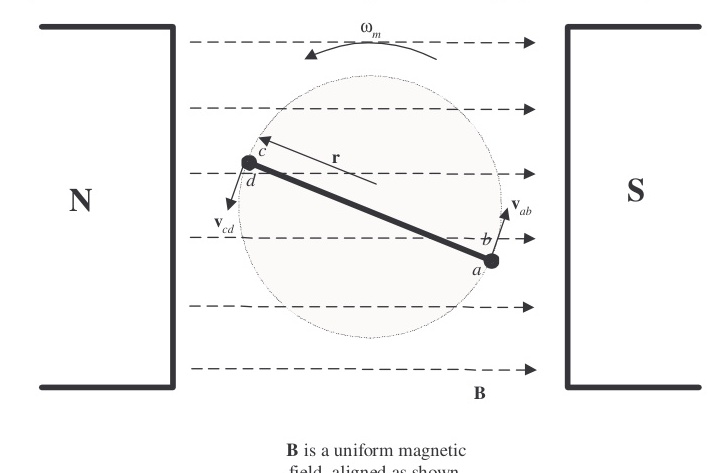
The simple loop rotating in a uniform magnetic field shown in Figure 4-1 has the following characteristics:
B=0.5 T to the rightr=0.1 m
l=0.5 mω=103 rad/s
(a) Calculate the voltage etot(t) induced in this rotating loop.
(b) Suppose that a 5 Ω resistor is connected as a load across the terminals of the loop. Calculate the current that would flow through the resistor.
(c) Calculate the magnitude and direction of the induced torque on the loop for the conditions in (b).
(d) Calculate the electric power being generated by the loop for the conditions in (b).
(e) Calculate the mechanical power being consumed by the loop for the conditions in (b). How does this number compare to the amount of electric power being generated by the loop?
Solution
(a) The induced voltage on a simple rotating loop is given by:
eind(t)=2rωBlsinωt(4-8)
eind(t)=2(0.1 m)(103 rad/s)(0.5 T)(0.5 m)sin103t
eind(t)=5.15sin103t V
(b) If a 5 Ω resistor is connected as a load across the terminals of the loop, the current flow would be:
i(t)=Reind=5 Ω5.15sin103t V=1.03sin103t A
(c) The induced torque would be:
τind(t)=2rilBsinθ(4-17)
τind(t)=2(0.1 m)(1.03sinωt A)(0.5 m)(0.5 T)sinωt
τind(t)=0.0515sin2ωt N⋅m, counterclockwise
(d) The instantaneous power generated by the loop is:
P(t)=eindi=(5.15sinωt V)(1.03sinωt A)=5.30sin2ωt W
The average power generated by the loop is:
Pave=T1∫T5.30sin2ωtdt=2.65 W
(e) The mechanical power being consumed by the loop is:
P=τindω=(0.0515sin2ωt V)(103 rad/s)=5.30sin2ωt W
Note that the amount of mechanical power consumed by the loop is equal to the amount of electrical power created by the loop. This machine is acting as a generator, converting mechanical power into electrical power.
Problem 4-2
Develop a table showing the speed of magnetic field rotation in ac machines of 2,4,6,8,10,12, and 14 poles operating at frequencies of 50,60, and 400 Hz.
Solution
The equation relating the speed of magnetic field rotation to the number of poles and electrical frequency is:
nm=P120fe
The resulting table is:
| Number of Poles | fe=50 Hz | fe=60 Hz | fe=400 Hz |
|---|---|---|---|
| 2 | 3000 r/min | 3600 r/min | 24000 r/min |
| 4 | 1500 r/min | 1800 r/min | 12000 r/min |
| 6 | 1000 r/min | 1200 r/min | 8000 r/min |
| 8 | 750 r/min | 900 r/min | 6000 r/min |
| 10 | 600 r/min | 720 r/min | 4800 r/min |
| 12 | 500 r/min | 600 r/min | 4000 r/min |
| 14 | 428.6 r/min | 514.3 r/min | 3429 r/min |
Problem 4-3
A three-phase four-pole winding is installed in 12 slots on a stator. There are 40 turns of wire in each slot of the windings. All coils in each phase are connected in series, and the three phases are connected in Δ. The flux per pole in the machine is 0.060 Wb, and the speed of rotation of the magnetic field is 1800 r/min.
(a) What is the frequency of the voltage produced in this winding?
(b) What are the resulting phase and terminal voltages of this stator?
Solution
(a) The frequency of the voltage produced in this winding is:
fe=120nmP=120(1800 r/min)(4 poles)=60 Hz
(b) There are 12 slots on this stator, with 40 turns of wire per slot. Since this is a four-pole machine, there are two sets of coils (4 slots) associated with each phase. The voltage in the coils in one pair of slots is:
EA=2πNcϕf=2π(40 t)(0.060 Wb)(60 Hz)=640 V
There are two sets of coils per phase, since this is a four-pole machine, and they are connected in series, so the total phase voltage is:
Vϕ=2(640 V)=1280 V
Since the machine is Δ-connected, VL=Vϕ=1280 V.
Problem 4-4
A three-phase Y-connected 50-Hz two-pole synchronous machine has a stator with 2000 turns of wire per phase. What rotor flux would be required to produce a terminal (line-to-line) voltage of 6 kV?
Solution
The phase voltage of this machine should be Vϕ=VL/3=3464 V. The induced voltage per phase in this machine (which is equal to Vϕ at no-load conditions) is given by the equation:
EA=2πNcϕf
so:
ϕ=2πNcfEA=2π(2000 t)(50 Hz)3464 V=0.0078 Wb
Problem 4-5
Modify the MATLAB program in Example 4-1 by swapping the currents flowing in any two phases. What happens to the resulting net magnetic field?
Solution
This modification is very simple—just swap the currents supplied to two of the three phases.
% M-file: mag_field2.m
% M-file to calculate the net magnetic field produced
% by a three-phase stator.

% Set up the basic conditions
bmax = 1;               % Normalize bmax to 1
freq = 60;              % 60 Hz
w = 2*pi*freq;          % angular velocity (rad/s)

% First, generate the three component magnetic fields
t = 0:1/6000:1/60;
Baa = sin(w*t) .* (cos(0) + j*sin(0));
Bbb = sin(w*t+2*pi/3) .* (cos(2*pi/3) + j*sin(2*pi/3));
Bcc = sin(w*t-2*pi/3) .* (cos(-2*pi/3) + j*sin(-2*pi/3));

% Calculate Bnet
Bnet = Baa + Bbb + Bcc;

% Calculate a circle representing the expected maximum
% value of Bnet
circle = 1.5 * (cos(w*t) + j*sin(w*t));

% Plot the magnitude and direction of the resulting magnetic
% fields. Note that Baa is black, Bbb is blue, Bcc is
% magenta, and Bnet is red.
for ii = 1:length(t)
    % Plot the reference circle
    plot(circle, 'k');
    hold on;

    % Plot the four magnetic fields
    plot([0 real(Baa(ii))], [0 imag(Baa(ii))], 'k', 'LineWidth', 2);
    plot([0 real(Bbb(ii))], [0 imag(Bbb(ii))], 'b', 'LineWidth', 2);
    plot([0 real(Bcc(ii))], [0 imag(Bcc(ii))], 'm', 'LineWidth', 2);
    plot([0 real(Bnet(ii))], [0 imag(Bnet(ii))], 'r', 'LineWidth', 3);
    axis square;
    axis([-2 2 -2 2]);
    drawnow;
    hold off;
end
When this program executes, the net magnetic field rotates clockwise, instead of counterclockwise.
Problem 4-6
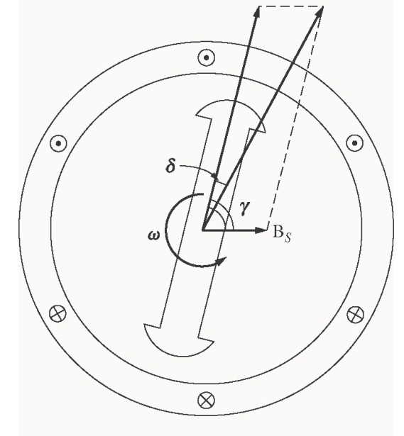
If an ac machine has the rotor and stator magnetic fields shown in Figure P4-1, what is the direction of the induced torque in the machine? Is the machine acting as a motor or generator?
Solution
Since τind=kBR×Bnet, the induced torque is clockwise, opposite the direction of motion. The machine is acting as a generator.
Problem 4-7
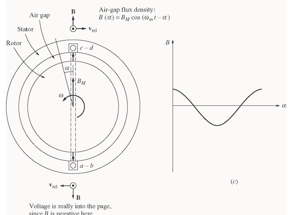
The flux density distribution over the surface of a two-pole stator of radius r and length l is given by:
B=BMcos(ωmt−α)(4-37b)
Prove that the total flux under each pole face is:
ϕ=2rlBM
Solution
The total flux under a pole face is given by the equation:
ϕ=∫B⋅dA
Under a pole face, the flux density B is always parallel to the vector dA, since the flux density is always perpendicular to the surface of the rotor and stator in the air gap. Therefore,
ϕ=∫BdA
A differential area on the surface of a cylinder is given by the differential length along the cylinder (dl) times the differential width around the radius of the cylinder (rdθ).
dA=(dl)(rdθ)where r is the radius of the cylinder
Therefore, the flux under the pole face is:
ϕ=∫Bdlrdθ
Since r is constant and B is constant with respect to l, this equation reduces to:
ϕ=rl∫Bdθ
Now, B=BMcos(ωt−α)=BMcosθ (when we substitute θ=ωt−α), so:
ϕ=rl∫Bdθ
ϕ=rl∫−π/2π/2BMcosθdθ=rlBM[sinθ]−π/2π/2=rlBM[1−(−1)]
ϕ=2rlBM
Problem 4-8
In the early days of ac motor development, machine designers had great difficulty controlling the core losses (hysteresis and eddy currents) in machines. They had not yet developed steels with low hysteresis, and were not making laminations as thin as the ones used today. To help control these losses, early ac motors in the USA were run from a 25 Hz ac power supply, while lighting systems were run from a separate 60 Hz ac power supply.
(a) Develop a table showing the speed of magnetic field rotation in ac machines of 2,4,6,8,10,12, and 14 poles operating at 25 Hz. What was the fastest rotational speed available to these early motors?
(b) For a given motor operating at a constant flux density B, how would the core losses of the motor running at 25 Hz compare to the core losses of the motor running at 60 Hz?
(c) Why did the early engineers provide a separate 60 Hz power system for lighting?
Solution
(a) The equation relating the speed of magnetic field rotation to the number of poles and electrical frequency is:
nm=P120fe
The resulting table is:
| Number of Poles | fe=25 Hz |
|---|---|
| 2 | 1500 r/min |
| 4 | 750 r/min |
| 6 | 500 r/min |
| 8 | 375 r/min |
| 10 | 300 r/min |
| 12 | 250 r/min |
| 14 | 214.3 r/min |
The highest possible rotational speed was 1500 r/min.
(b) Core losses scale according to the 1.5th power of the speed of rotation, so the ratio of the core losses at 25 Hz to the core losses at 60 Hz (for a given machine) would be:
ratio=(36001500)1.5=0.269 or 26.9%
(c) At 25 Hz, the light from incandescent lamps would visibly flicker in a very annoying way.